CNC Plasma Cutter Build
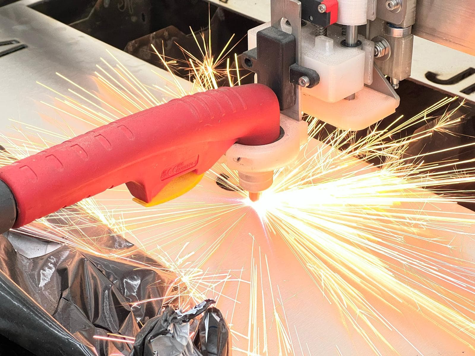
This project documents the design and fabrication of a fully custom CNC plasma cutting machine. It uses a gantry-style frame with belt-driven X and Y axes, a lead-screw-driven Z axis for torch height control, and an Arduino running GRBL firmware to interpret G-code from Fusion 360's CAM environment.
The goal was to build a capable plasma cutting platform at a fraction of the cost of commercial machines. Total build cost came in at roughly 1,030 EUR for materials, plus a significant amount of design time. Full CAD, print, laser-cut, and wiring files are available in the Downloads section.
1. Overview
The interactive model above shows the main assemblies colour-coded: base frame (green), X-axis (red), Y-axis (blue), Z-axis (yellow), and electronics enclosure (purple).
The machine has a usable cutting area of 1,100 x 800 mm, sized to accommodate commercially available sheet metal (typically 1,000 mm wide). The plasma cutter used is an R-Tech P51D.
All motion axes use GT2 timing belts (10 mm wide) rather than ball screws to keep weight and cost down while enabling the speeds needed for thin sheet metal.
2. Build process
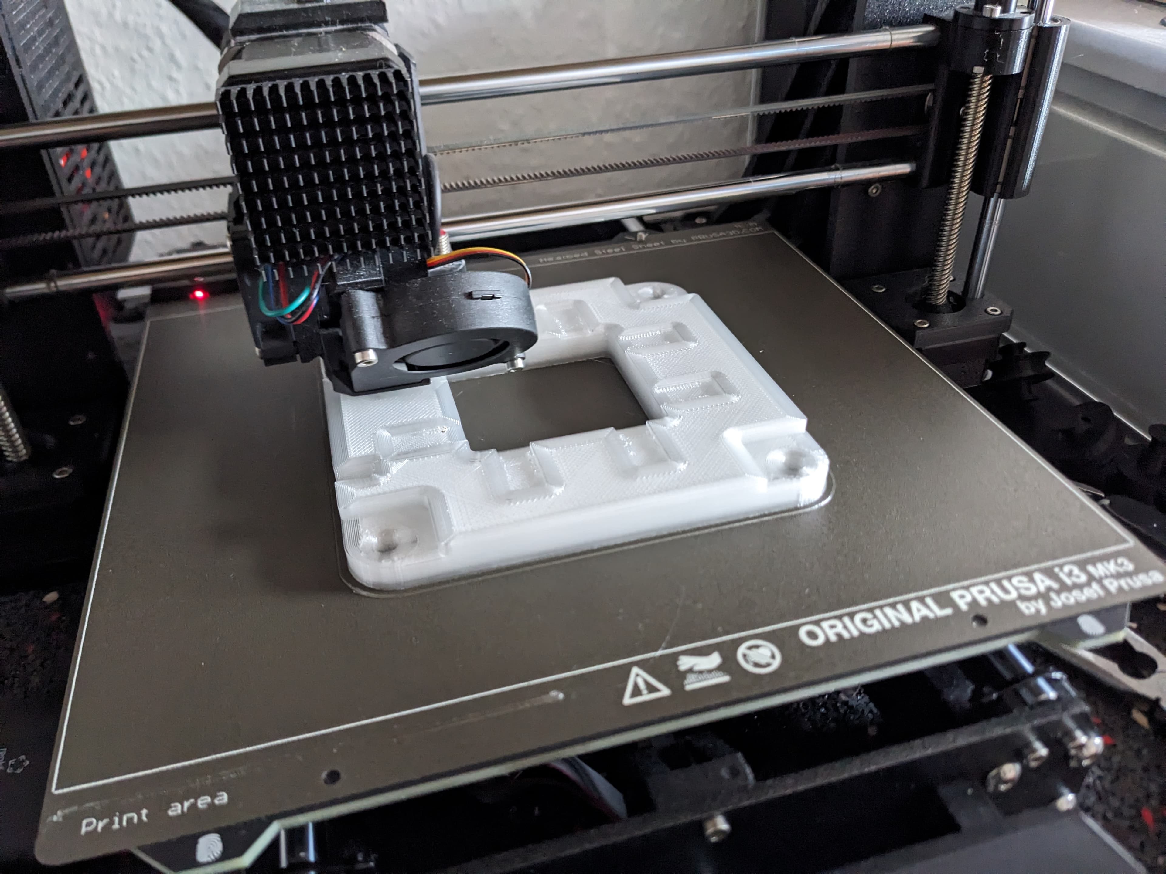
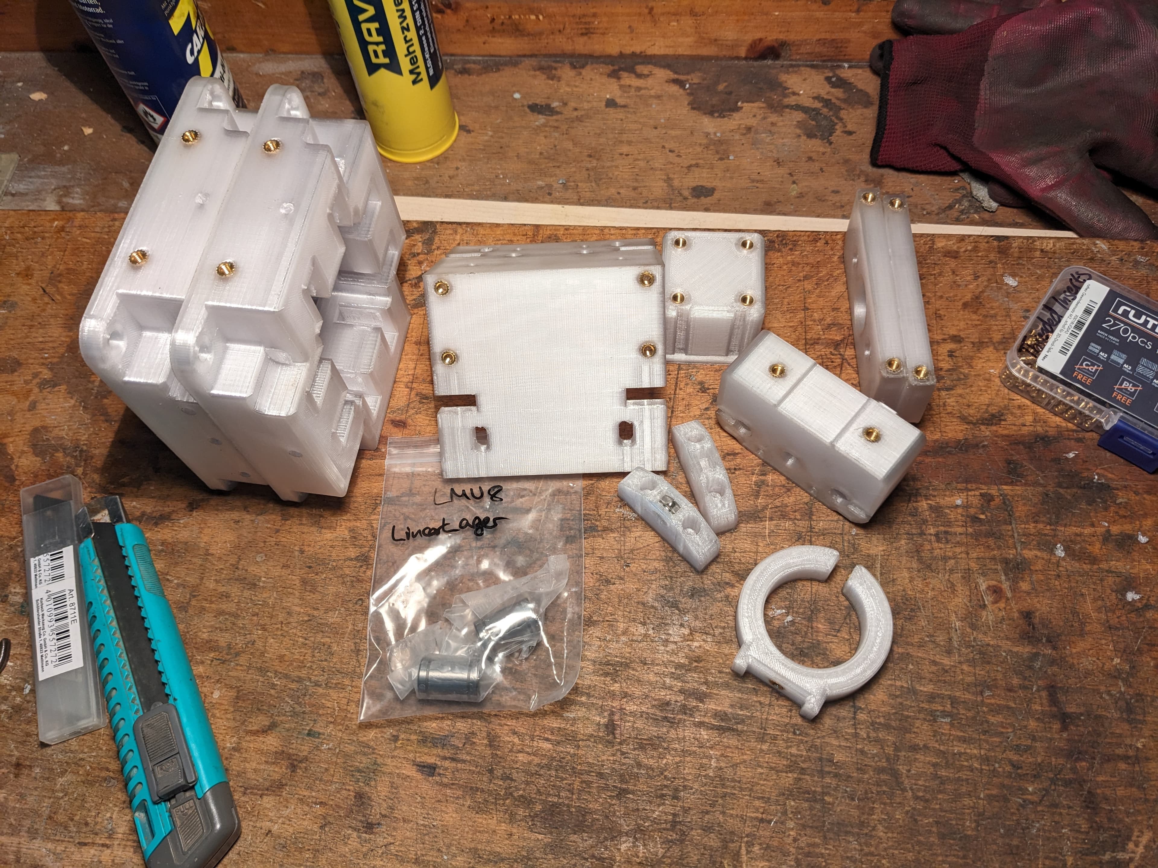
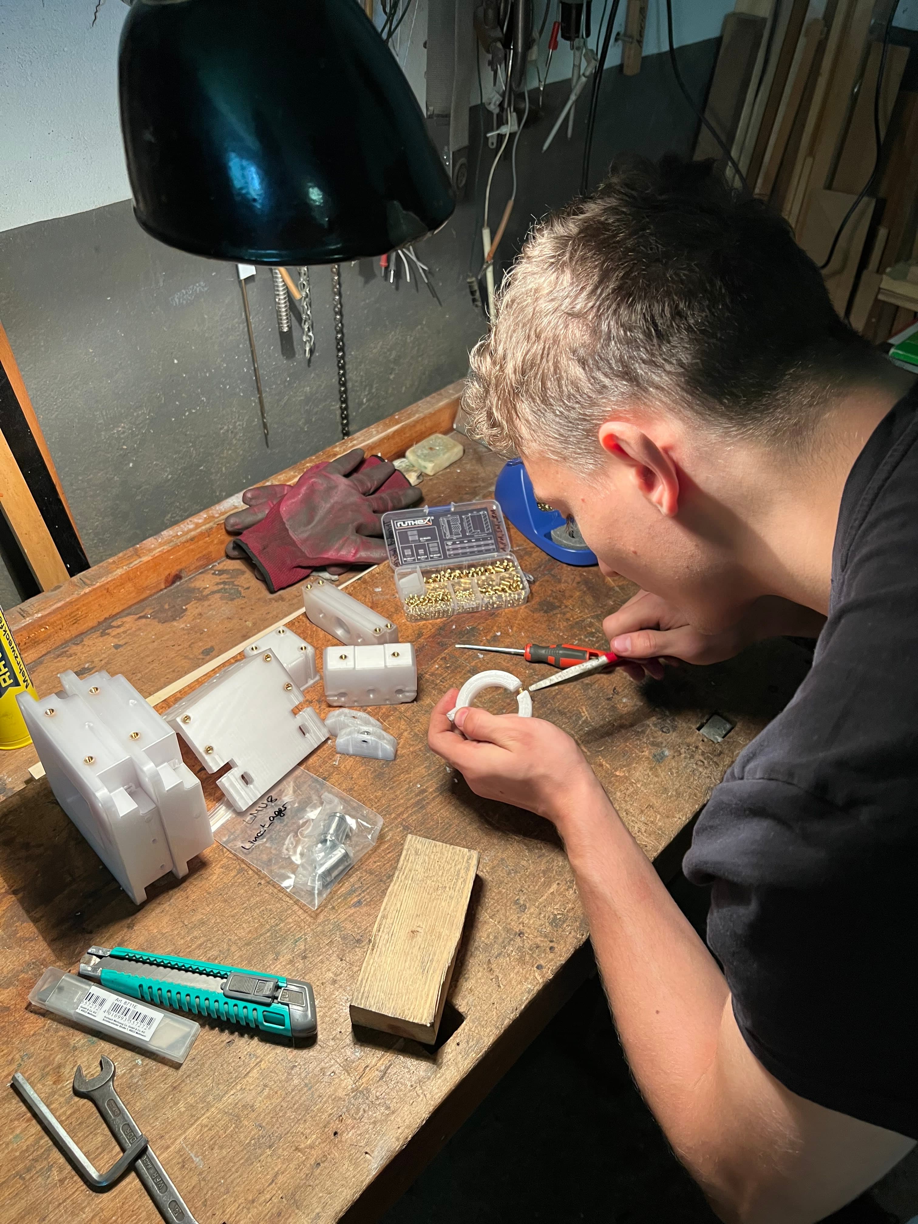
The build uses a mix of 3D-printed PETG parts (bearing blocks, carriages, tensioners, torch holder), laser-cut stainless steel plates (motor plates, backing plates), and commercially available square tubing. All 3D-printed parts were produced on a Prusa MK3s using Prusament PETG. Brass heat-set inserts provide threaded connections throughout.
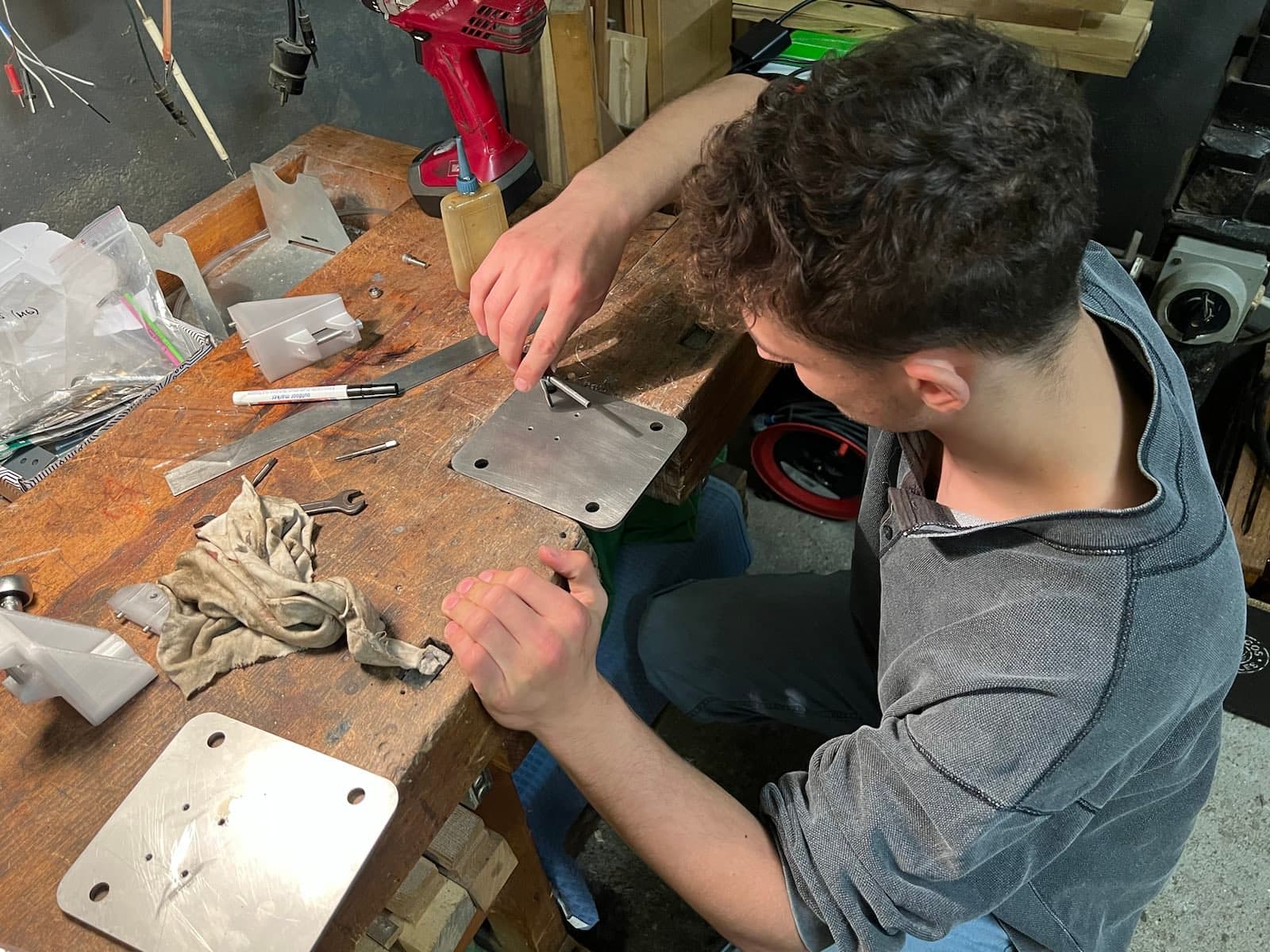
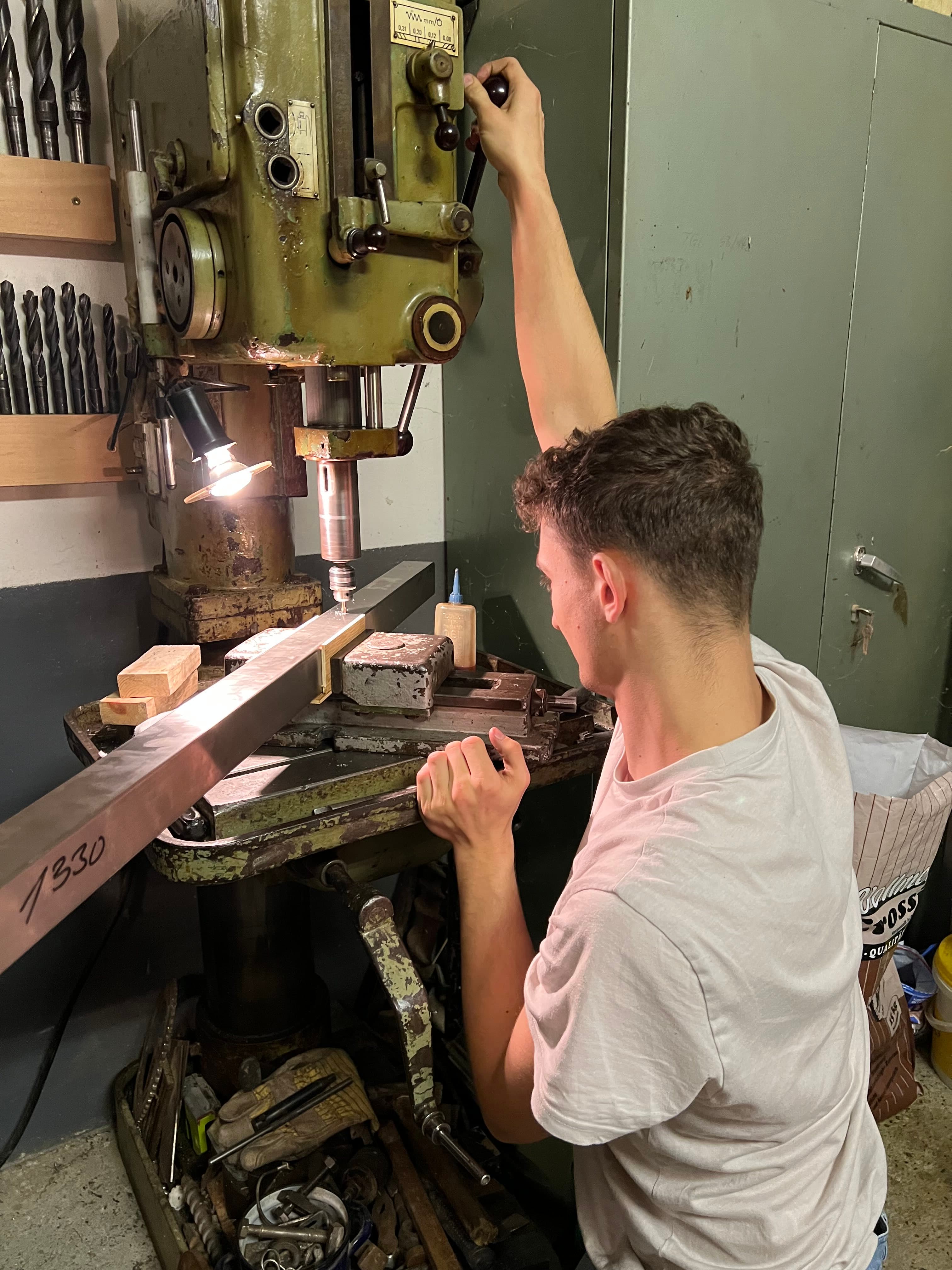
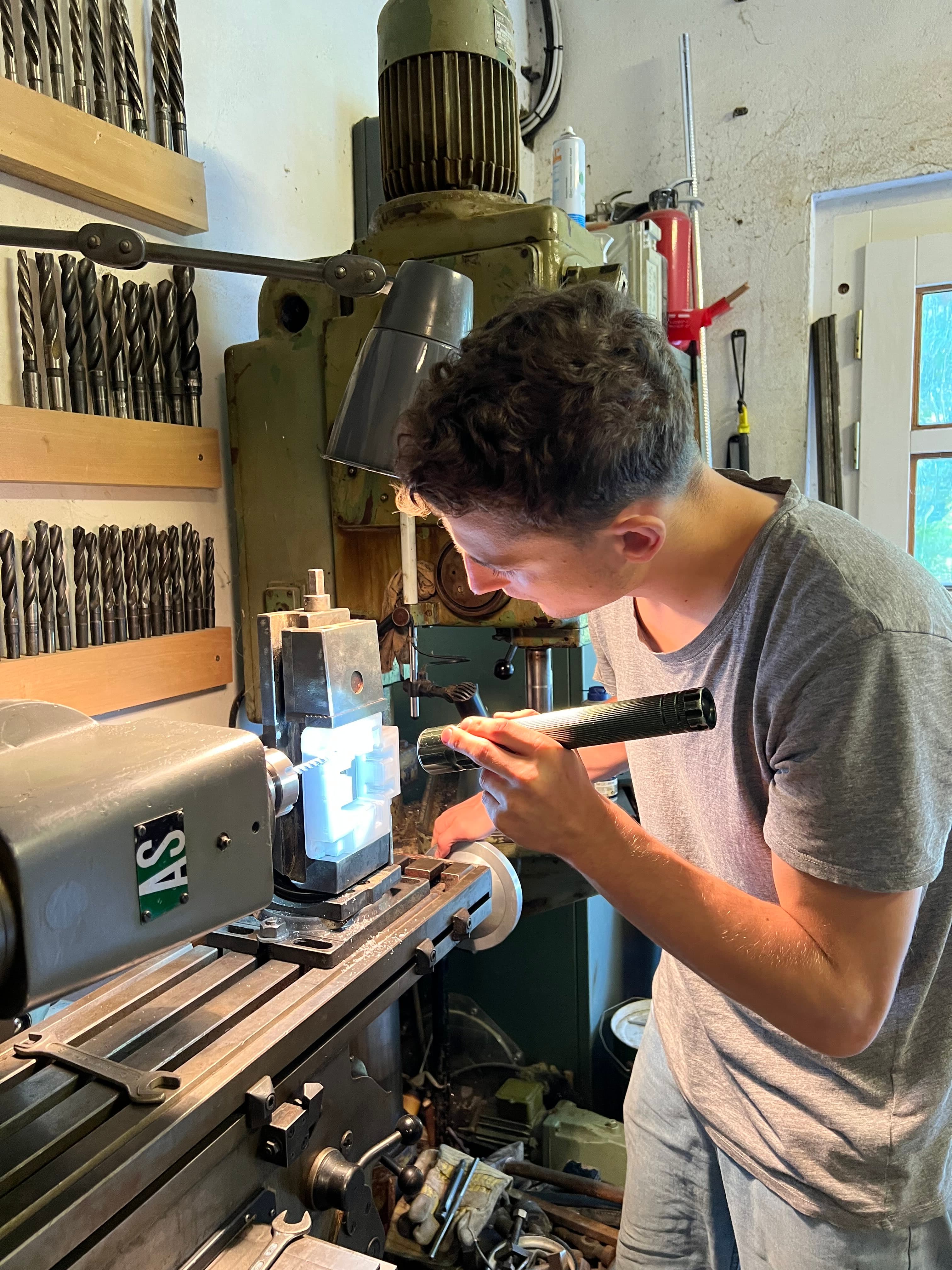
All metal fabrication was kept as simple as possible — everything can technically be done with hand tools, though decent workshop access helps. Sub-assemblies are documented in 2.1 through 2.6 below.
2.1 Frame
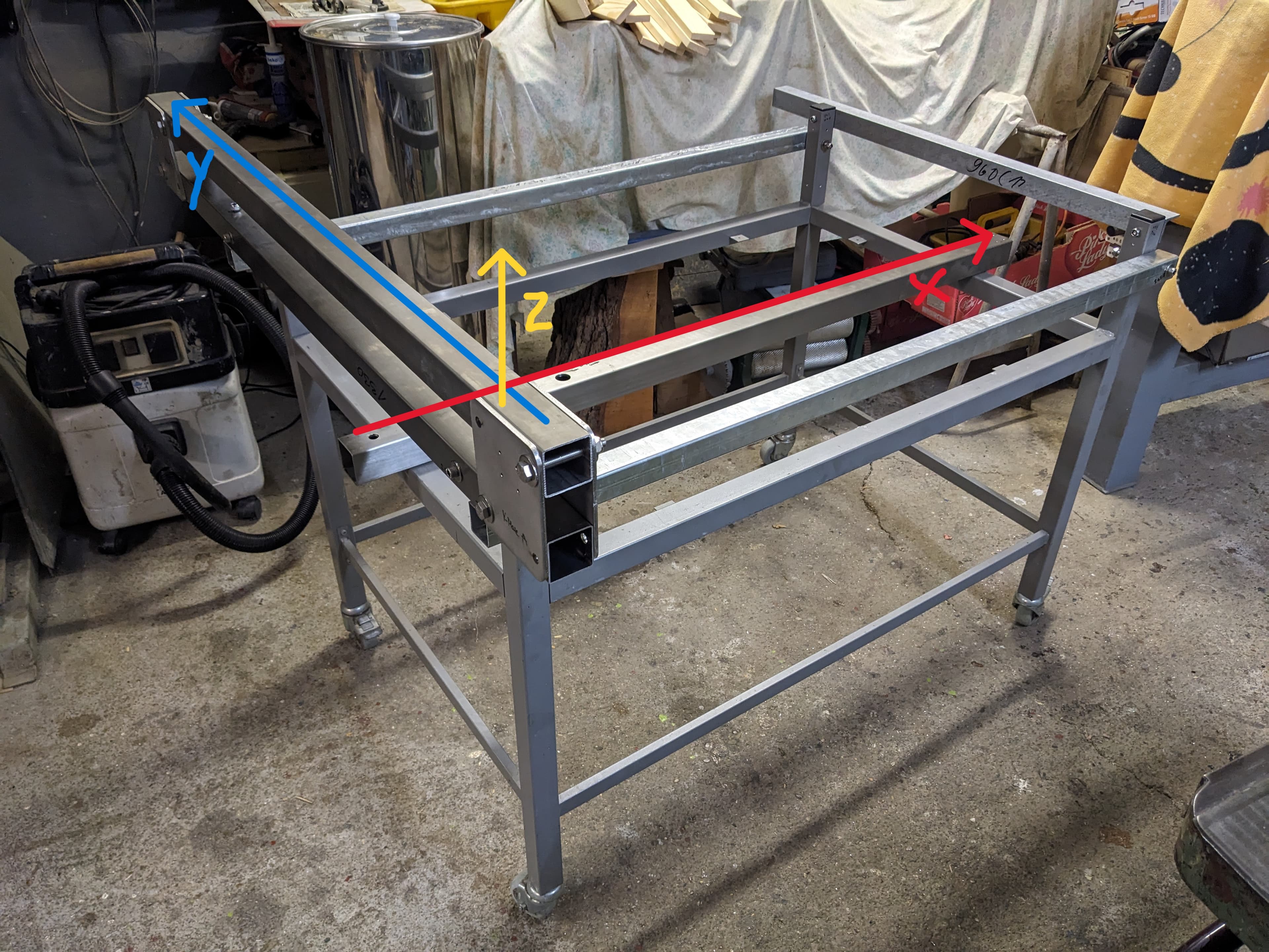
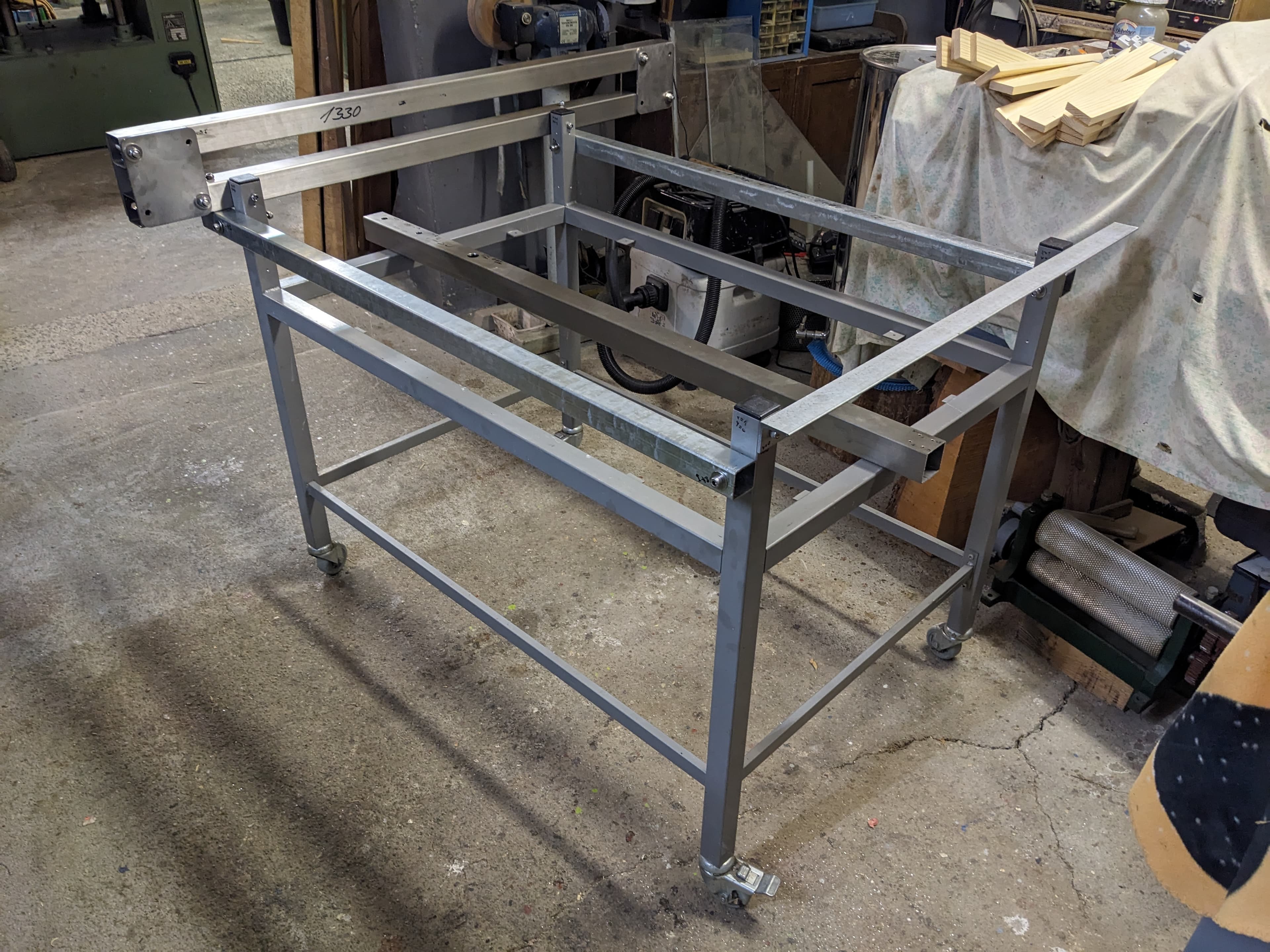
The base frame was salvaged from an existing scrap piece of 40x40x2 mm square steel tubing frame. The X (red) and Y axes (blue) are made from 50x50x2 mm stainless steel square tubing mounted to the existing frame. Two 40x40x2 mm galvanised square tube profiles run across in the X direction as supports, with a 40x40 mm angle profile on the right side providing additional support for the X-axis rail.
2.2 Electronics
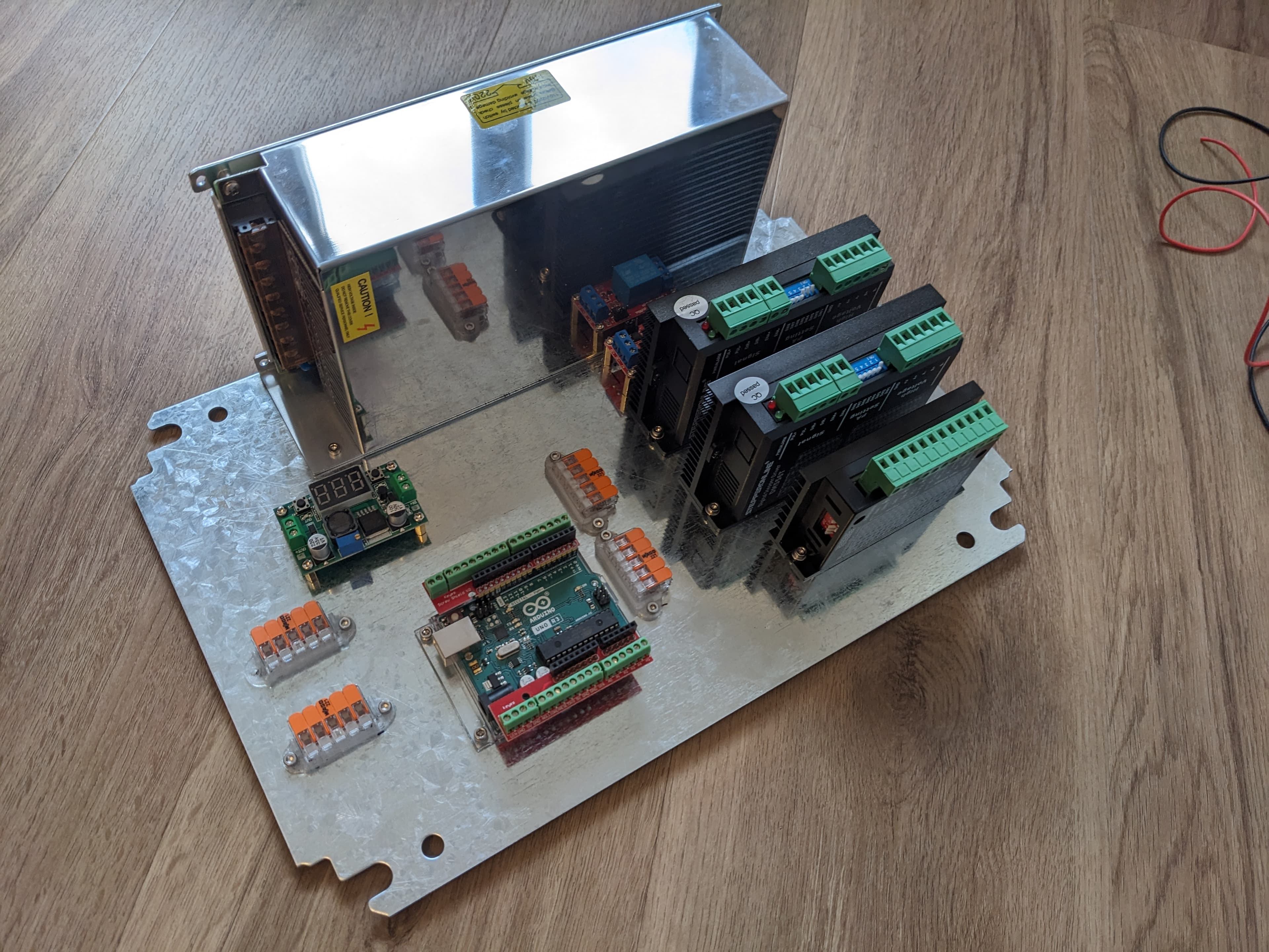
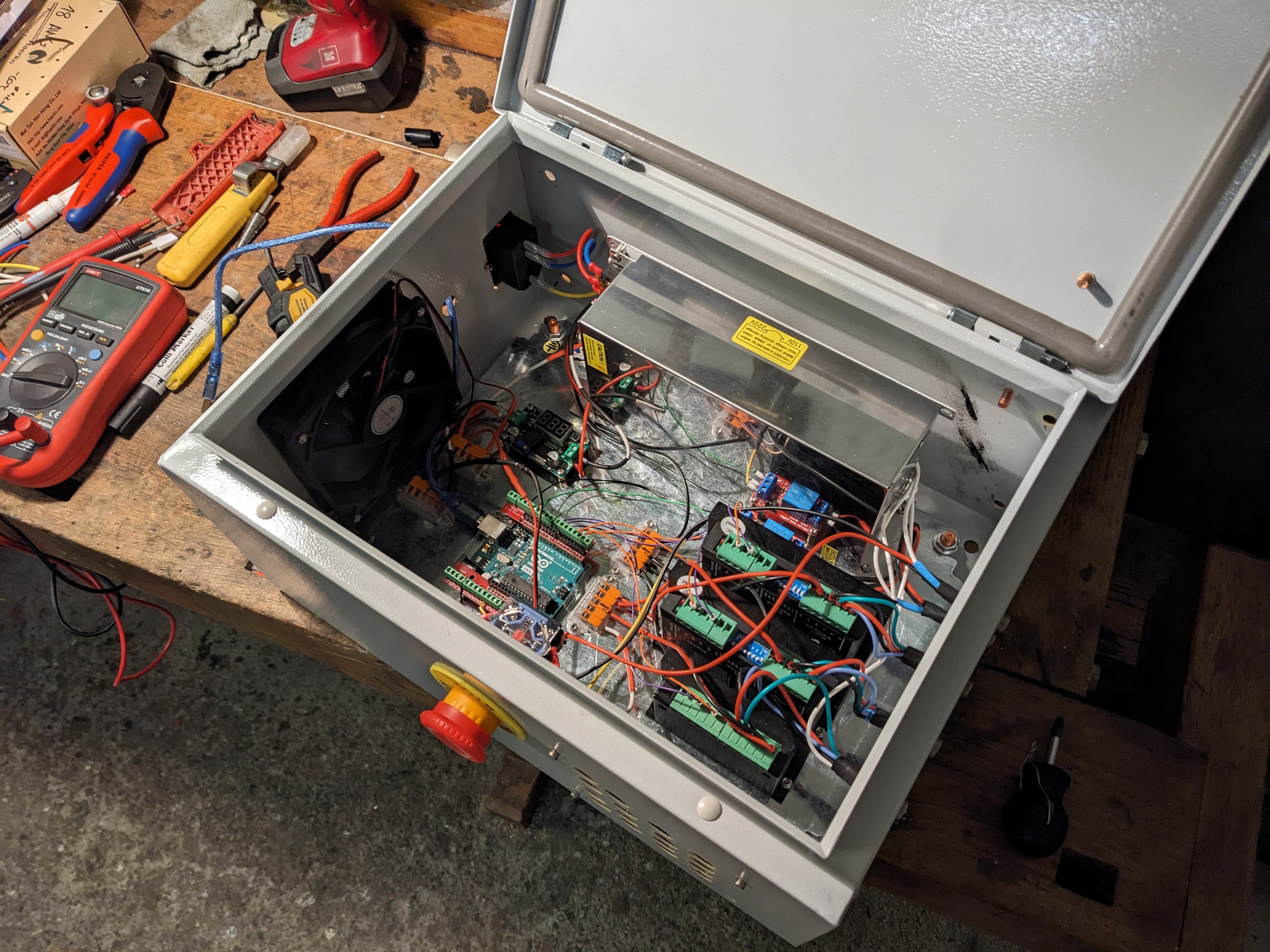
The electronics live in a 400x300x200mm IP-rated enclosure mounted to the floor plate (18mm multiplex) of the base frame.
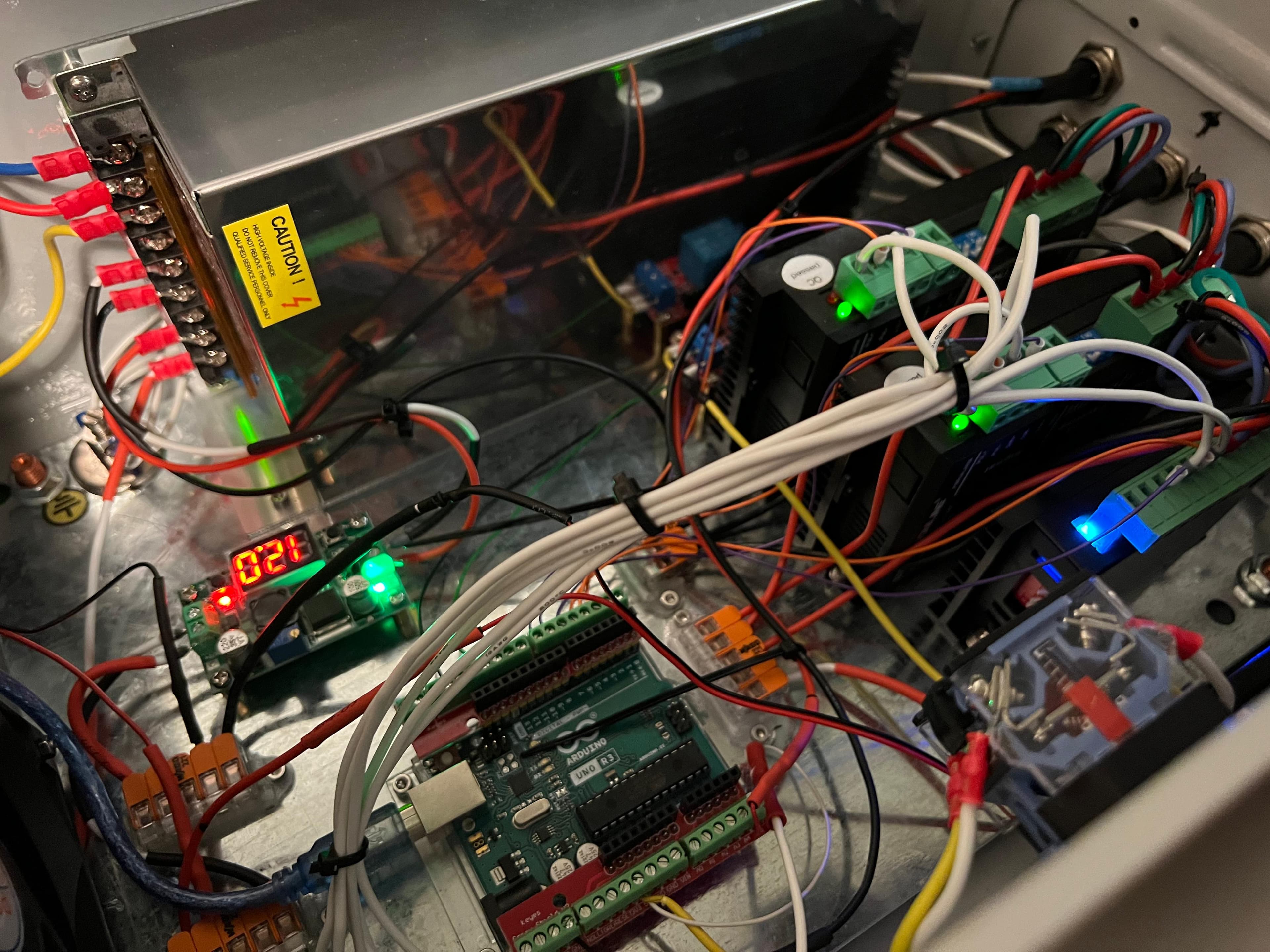
The system is controlled by an Arduino Uno and powered by a 36V 565W power supply and a 36V-to-12V step-down converter for the cooling fans.
The Arduino Uno runs GRBL firmware, receiving G-code over USB and generating step/direction pulses. Two DM556T drivers (24-48V, 5.6A) power the NEMA 23 motors on X and Y. A TB6600 driver (9-42V, 4A) drives the NEMA 17 on Z. A 5V relay on pin 13 (GRBL spindle output) switches the plasma torch trigger through the relay's normally-open contacts.
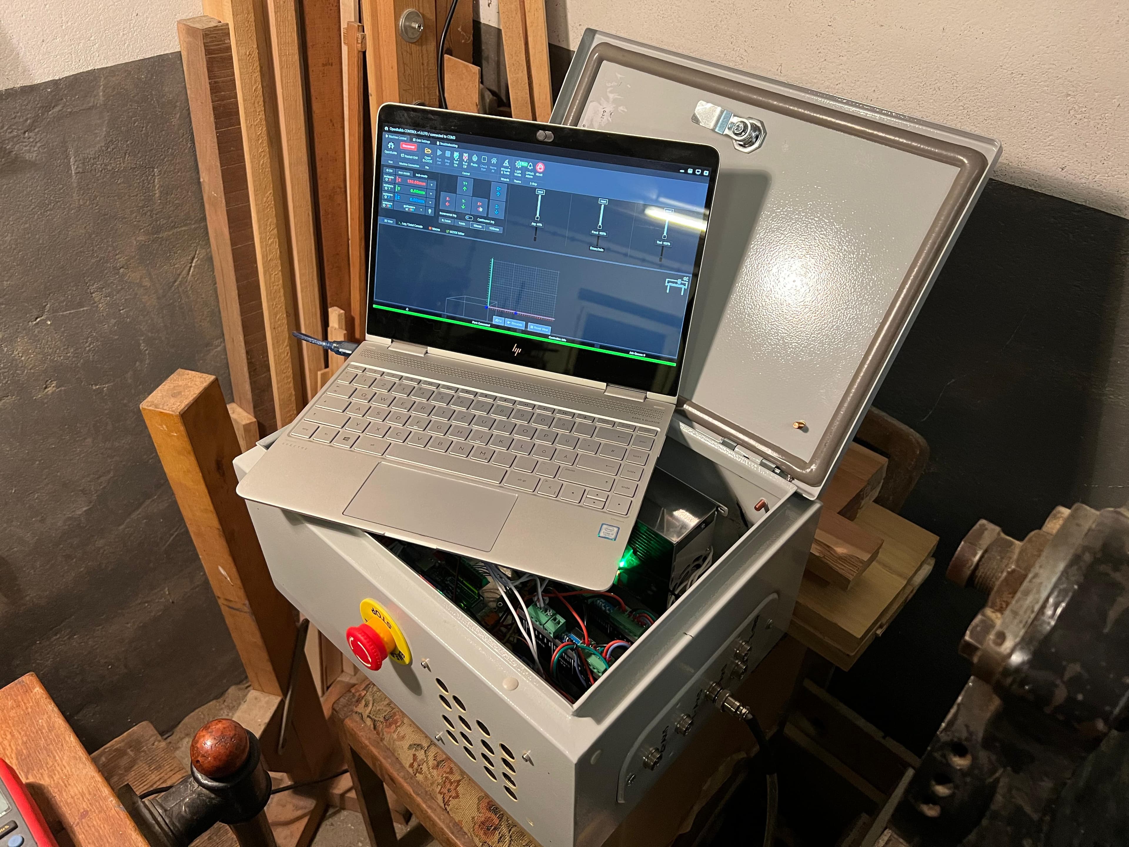
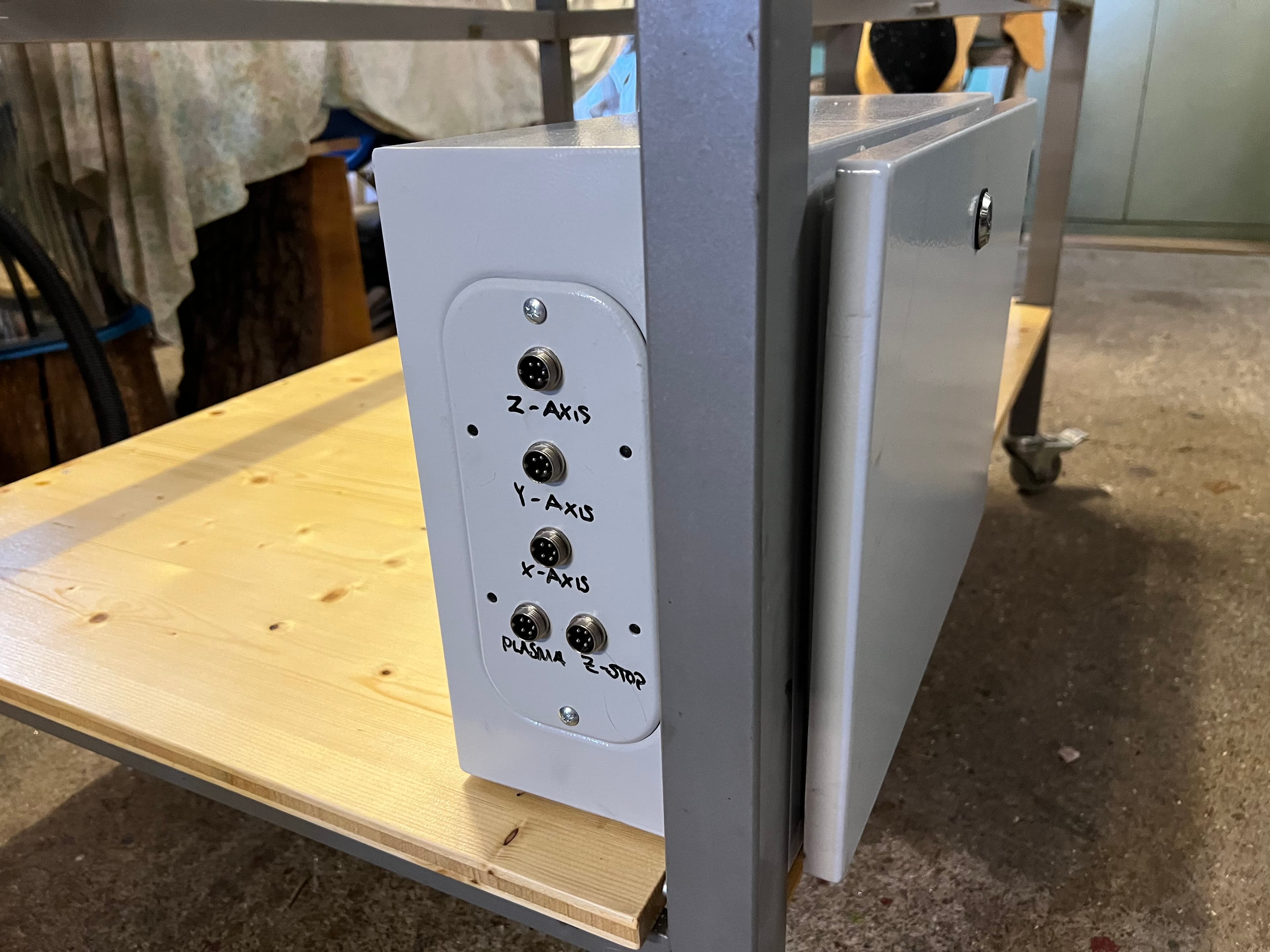
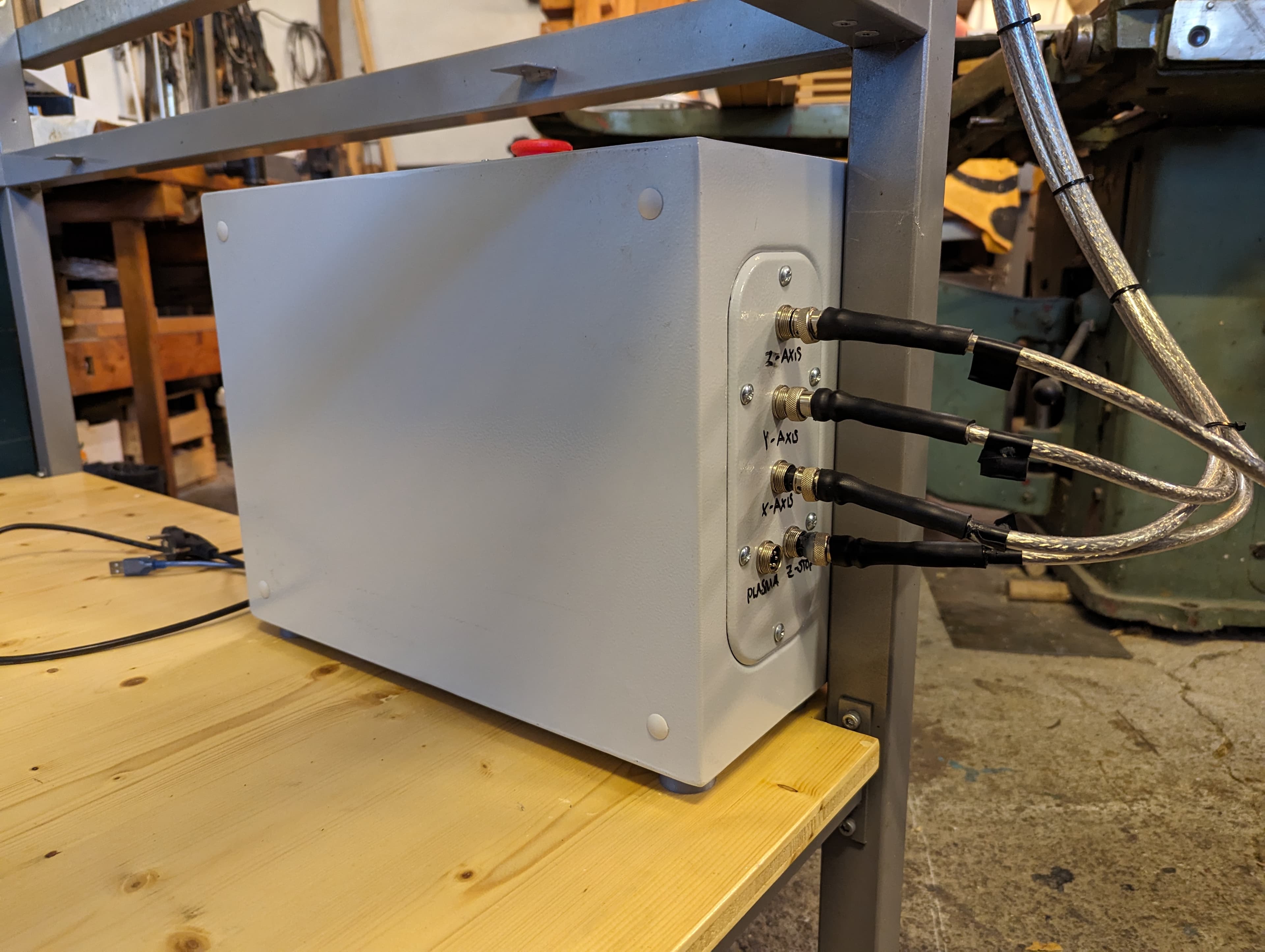
All cables outside of the electronics housing use shielded 4-strand wire (YSLY-CY-JZ 0.75 mm²) with GX16 5-pin aviation connectors for easy disconnection, shields grounded to the enclosure and CNC frame. An emergency stop switch is included — admittedly in a hard-to-reach spot :) Wiring diagrams are available in the Downloads section at the bottom of the page.
2.3 X-Axis
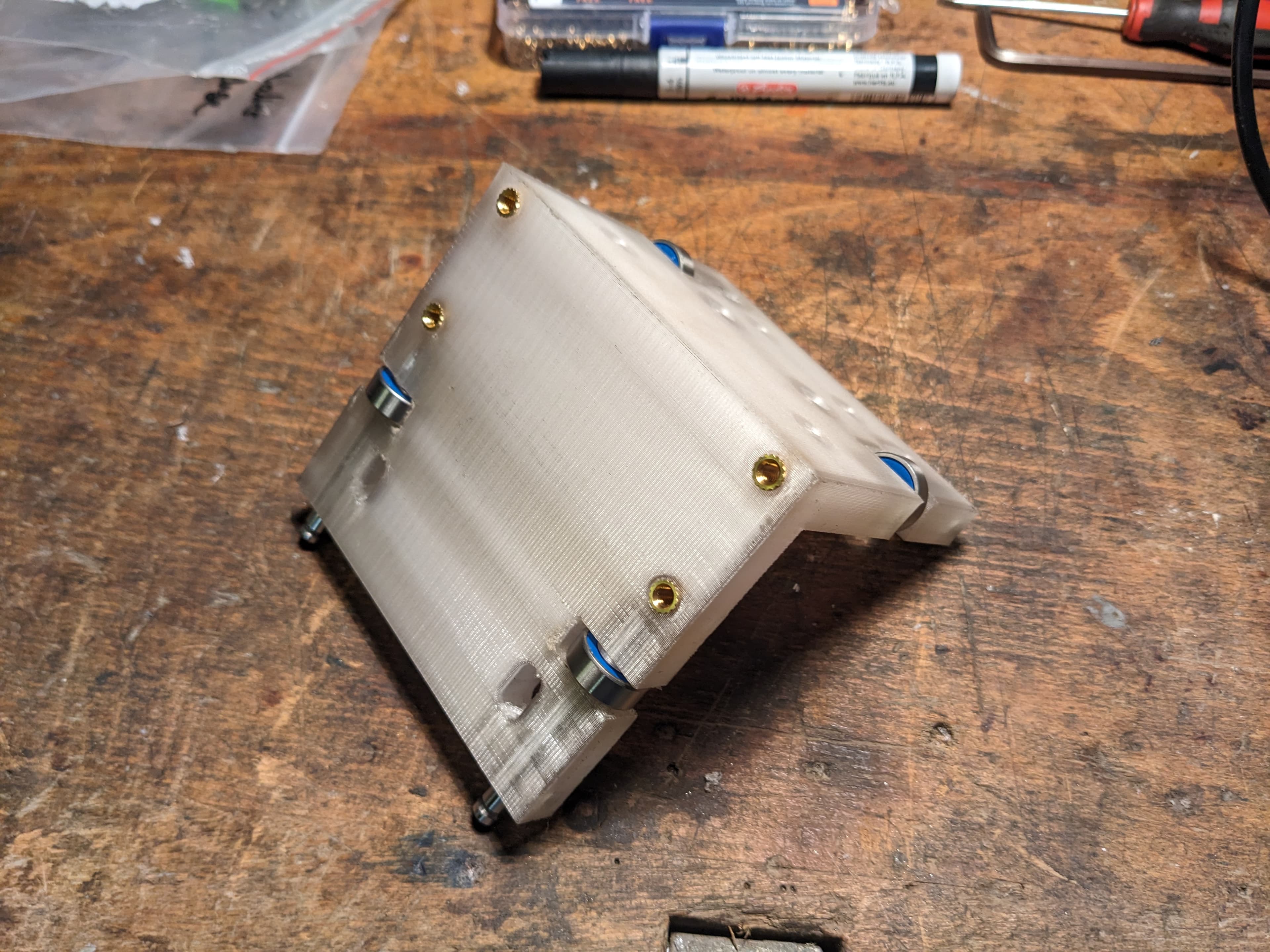
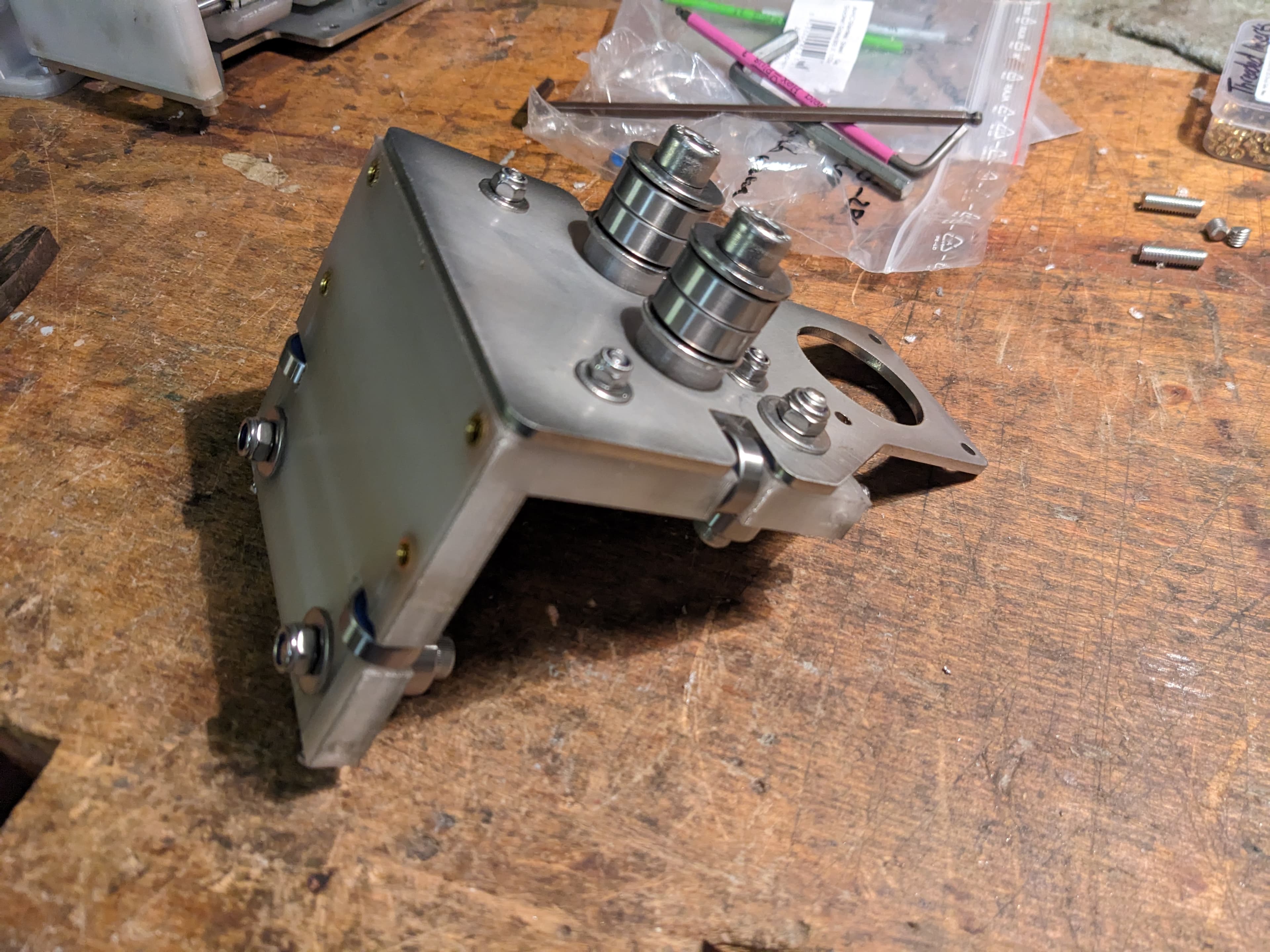
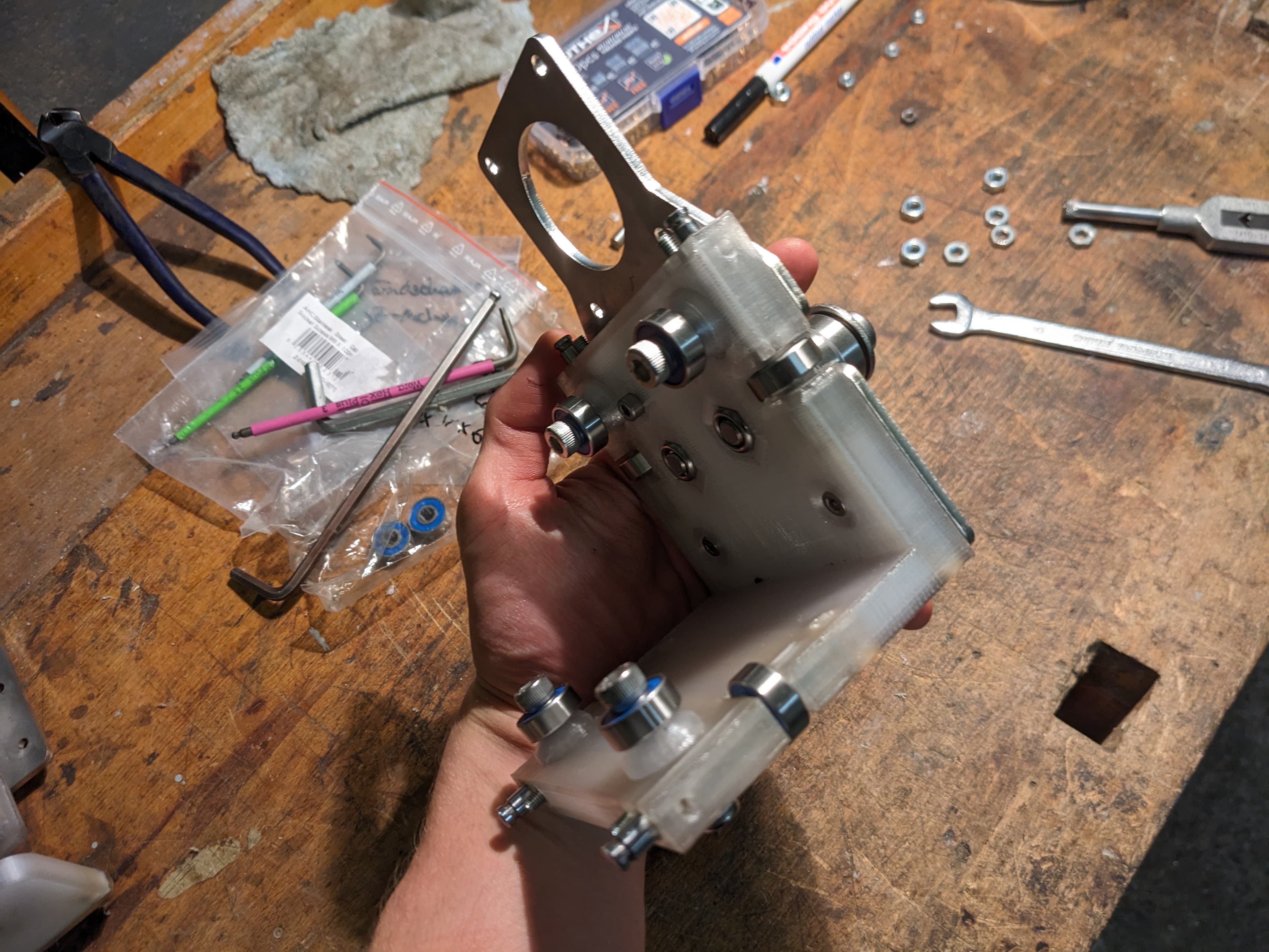
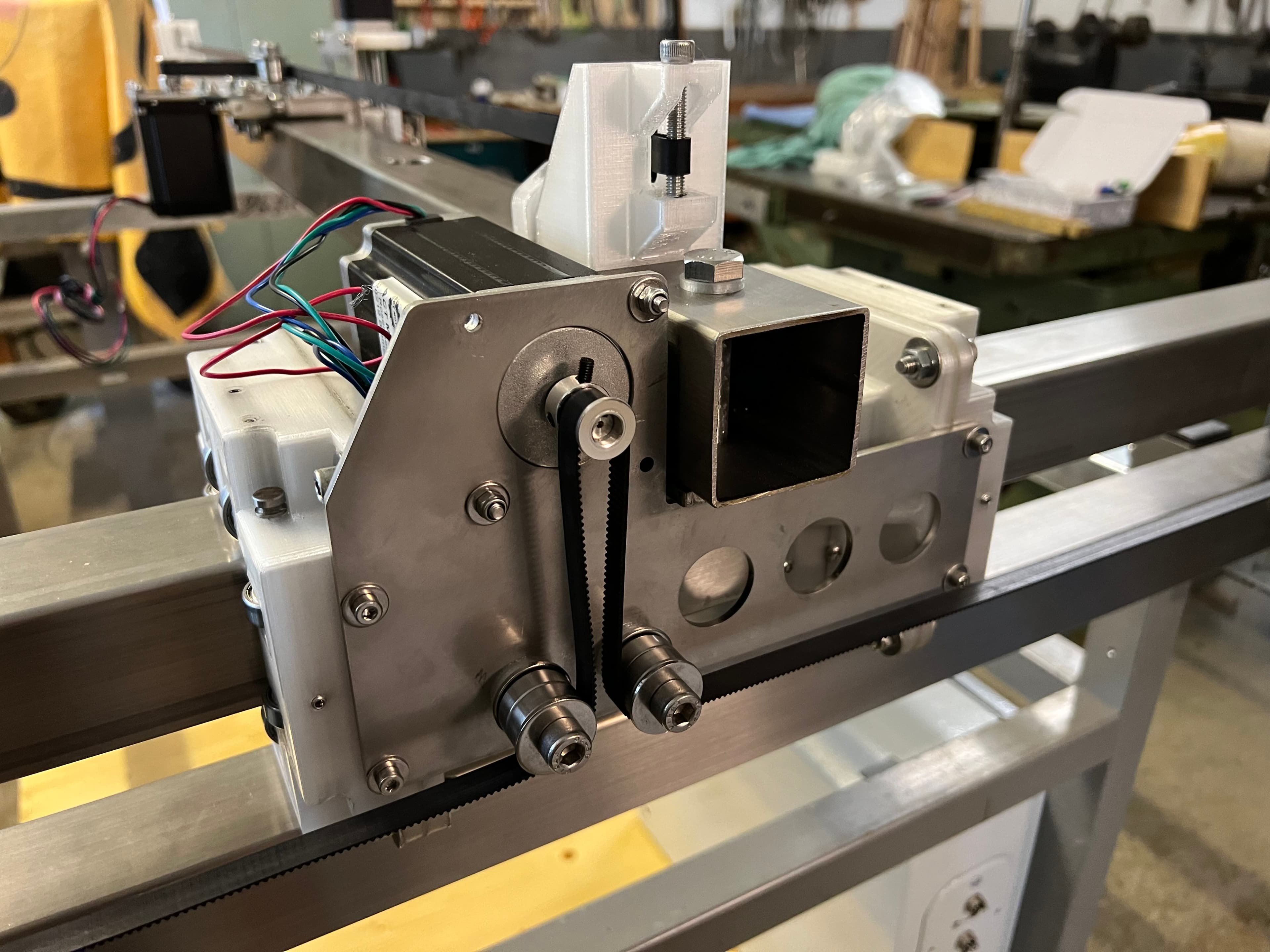
The X-axis beam is a 1,330 mm length of 50x50x2 mm stainless steel tube bolted to the Y-carriage. Shown here is the 3D-printed carriage that rides along the X-axis rail.
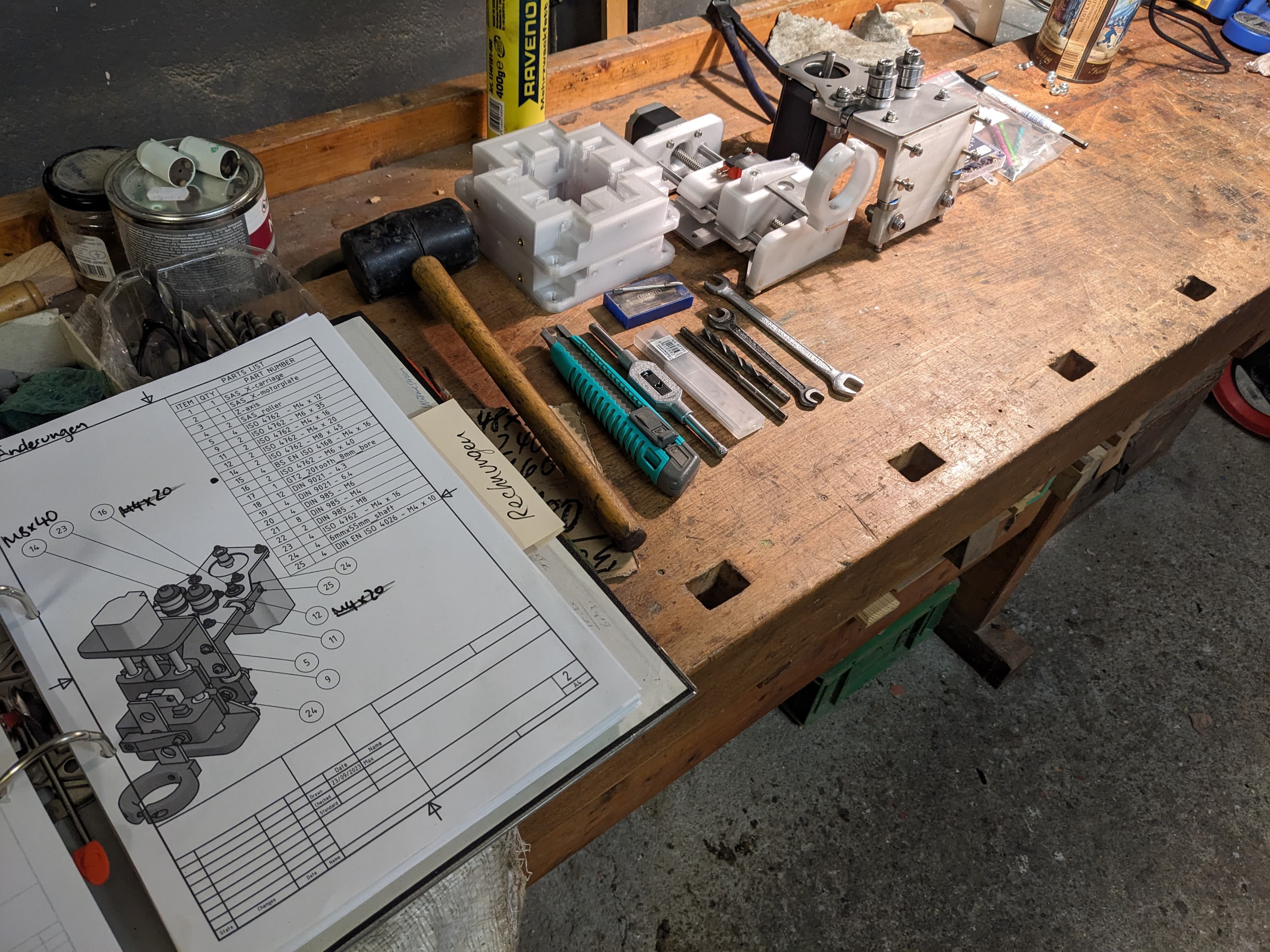
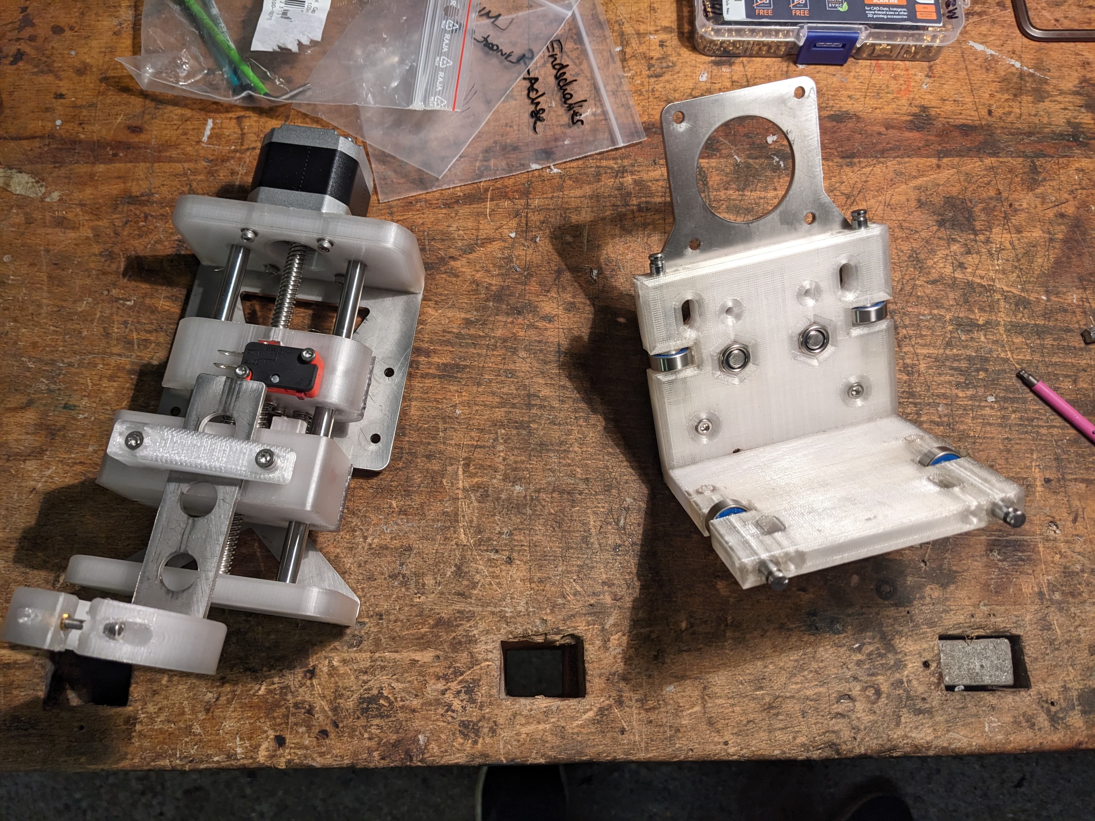
The X-carriage carries the Z-axis assembly and torch, using 606-2RS bearings on 6 mm precision shafts. The carriage body and roller standoffs are 3D-printed, while the motor plate (148x100x3 mm) is laser-cut steel.
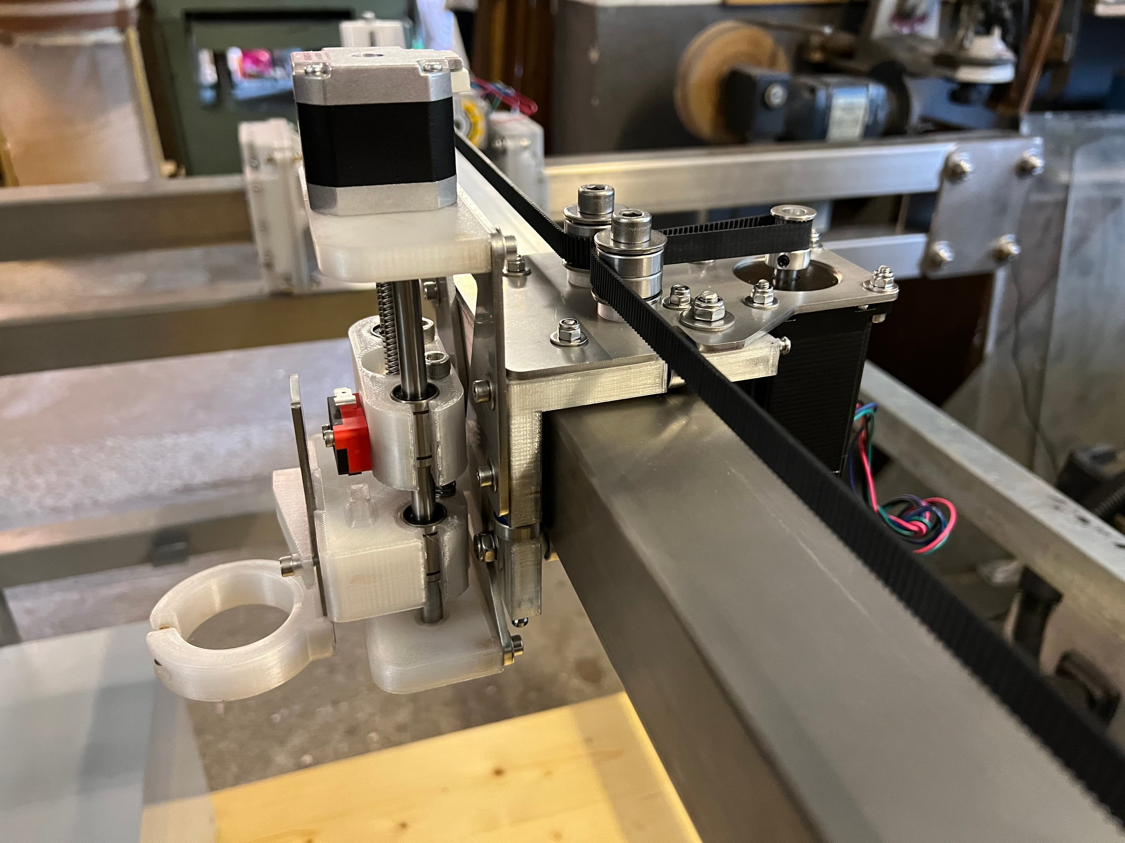
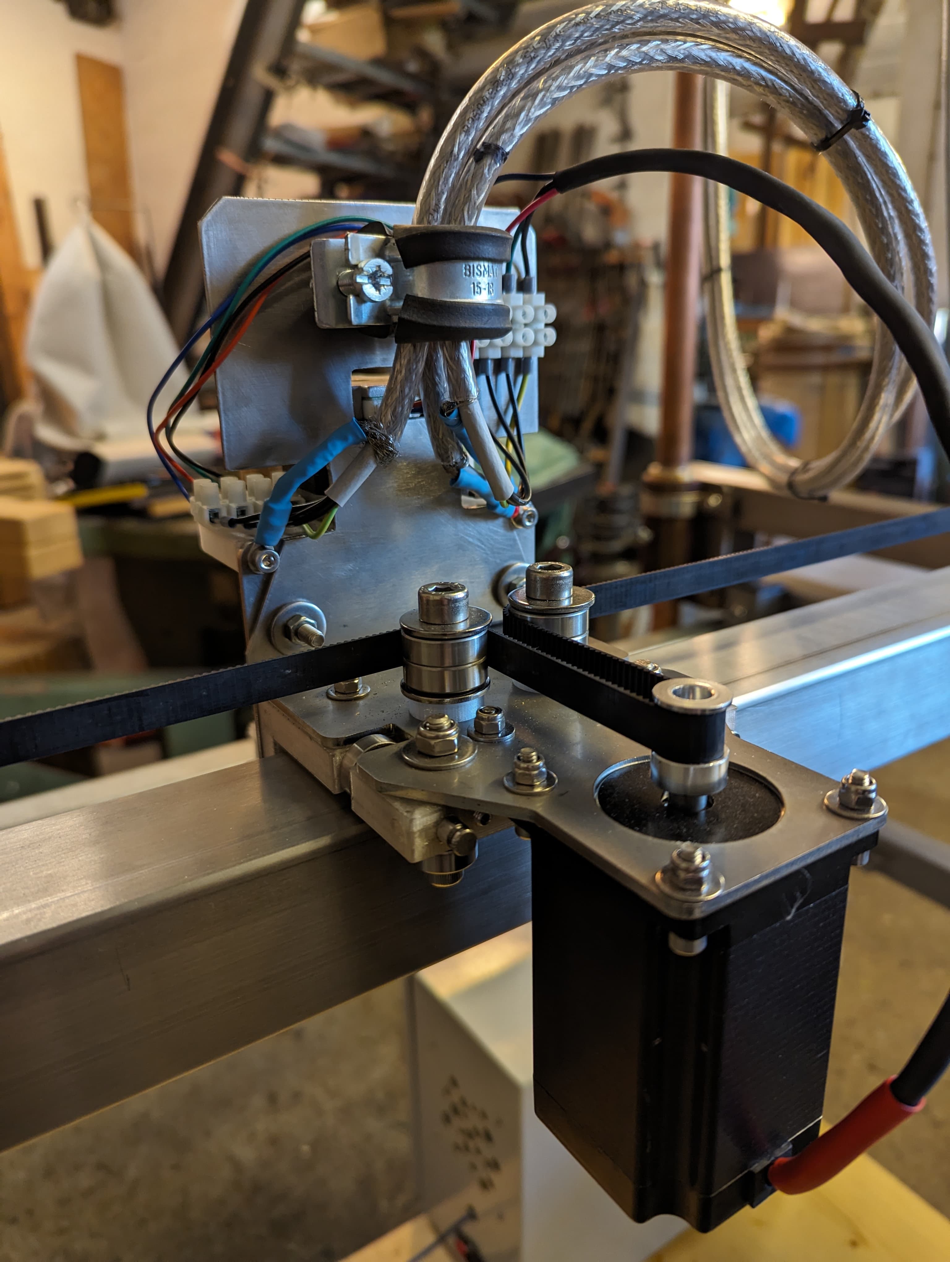
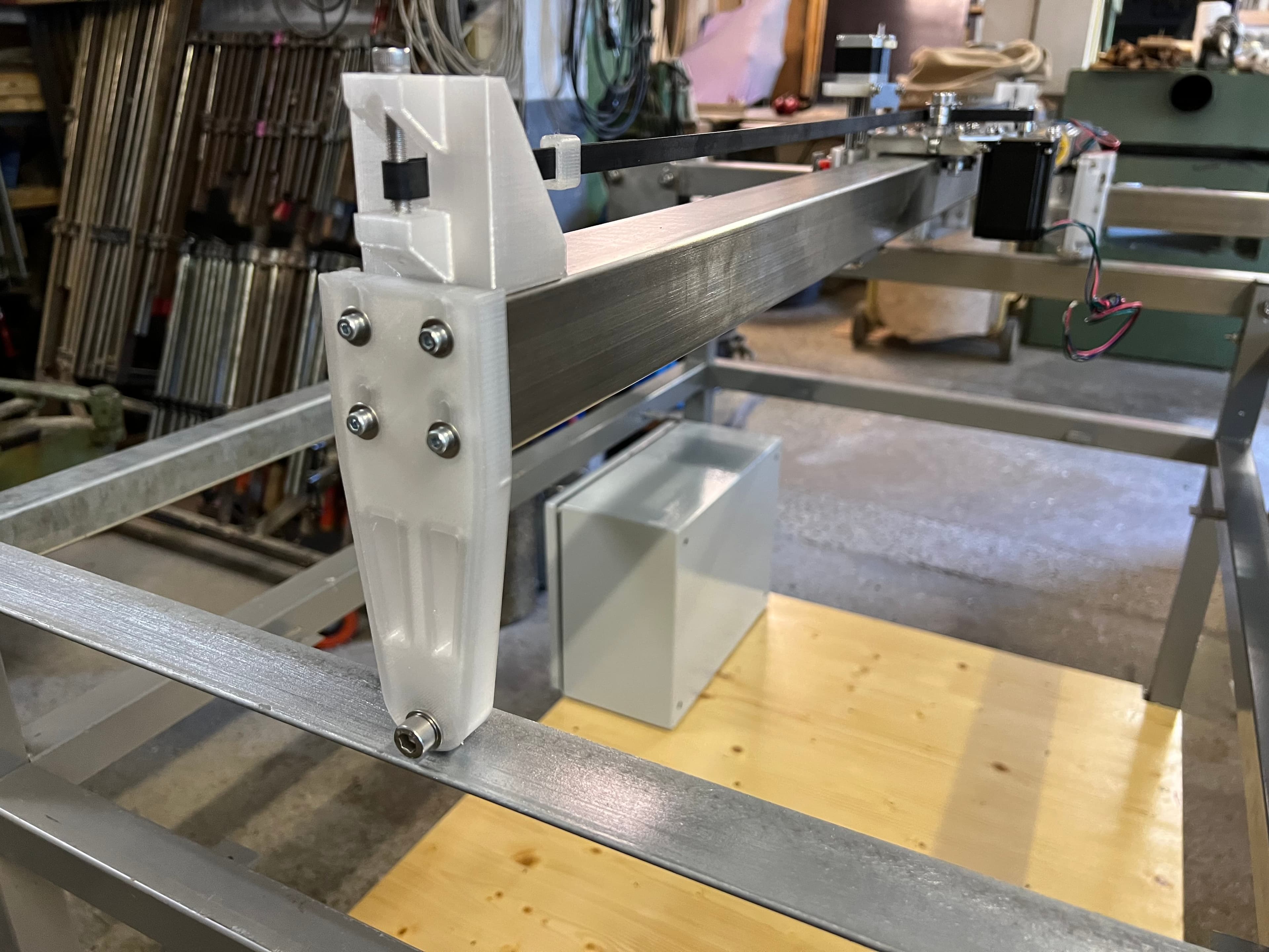
A NEMA 23 motor (2.4 Nm, 4A) drives the belt. A combination of slotted holes and set screws enable adjustability on the bearing mounts allowing fine-tuning of the carriage preload — tight enough to eliminate slop, loose enough for smooth travel. Due to the length of the X-axis it is supported on the far side with an adjustable roller assembly.
2.4 Y-Axis
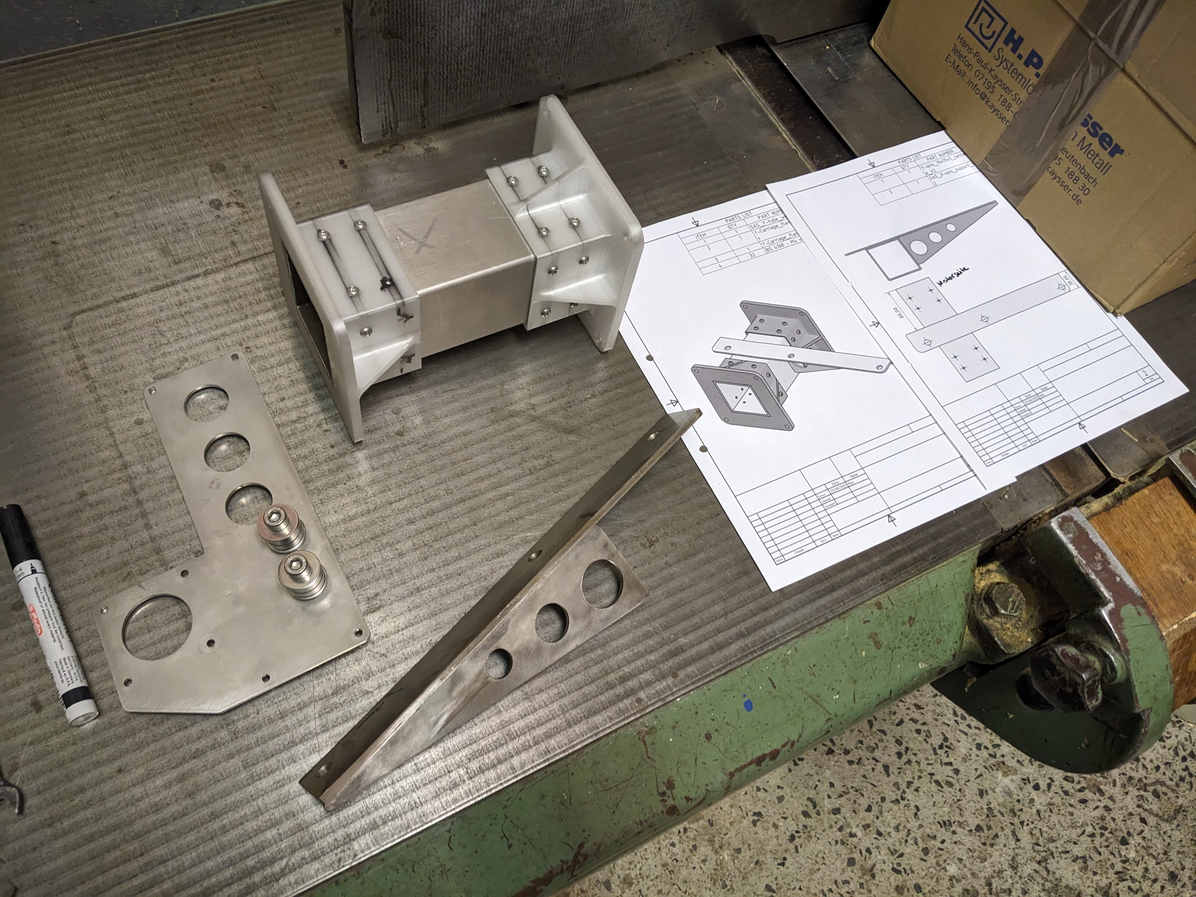
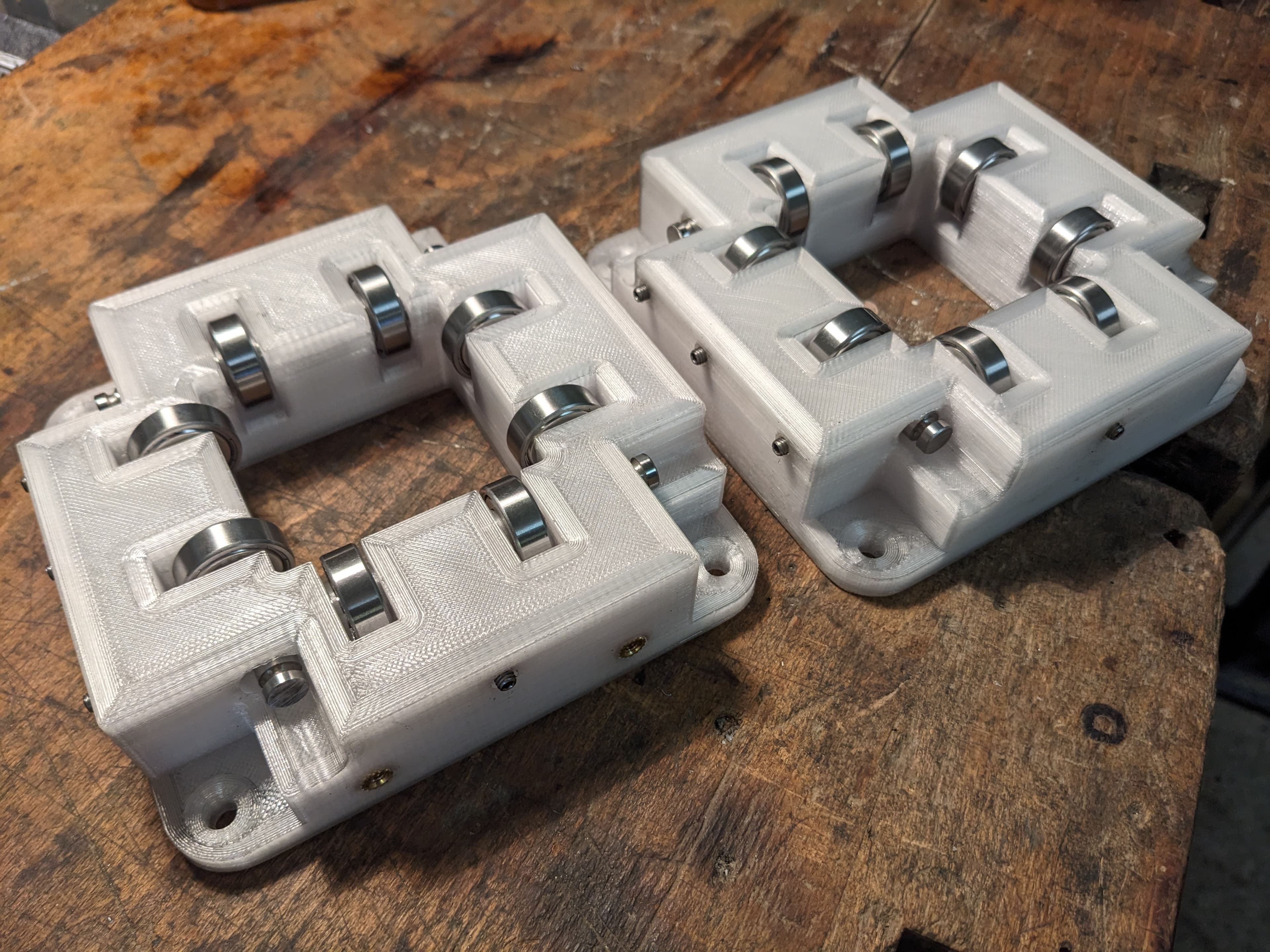
The Y-carriage is the most complex subassembly — it rides on these rails and carries the entire X-axis beam. It uses 3D-printed bearing blocks with 608zz bearings, adjustable via set screws in contact with the 8mm precision rods that serve as bearing shafts. Two sides allow for setting preload with one set screw (to bring bearings into contact) while the opposing sides use 3 set screws for fine adjustment of the carriage.
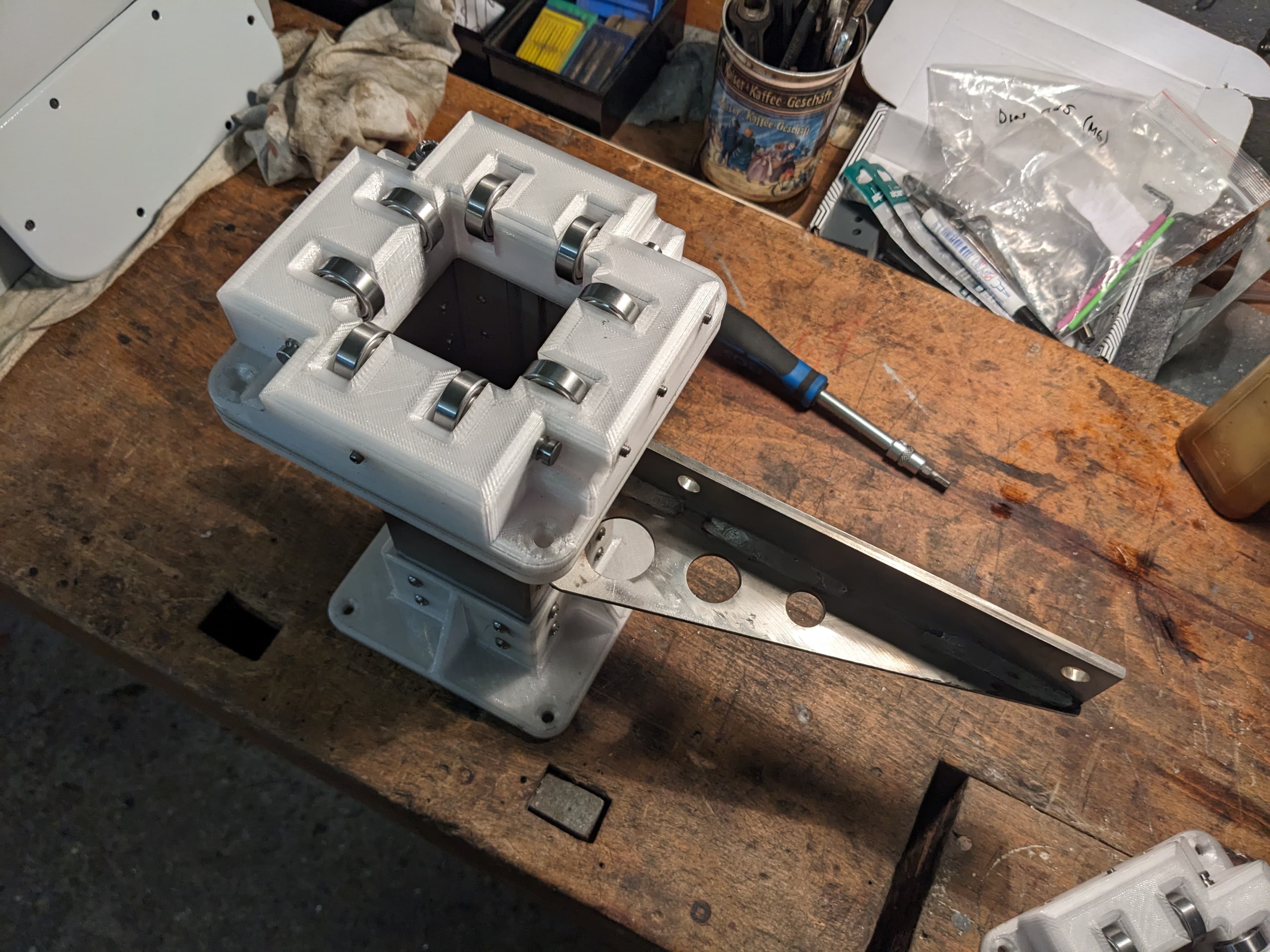
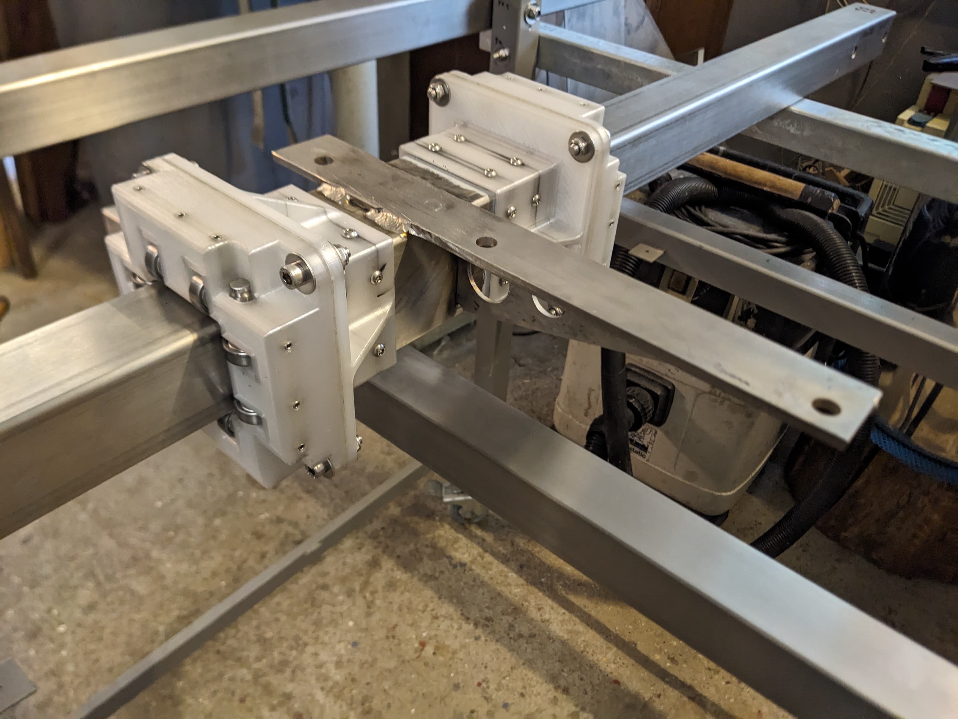
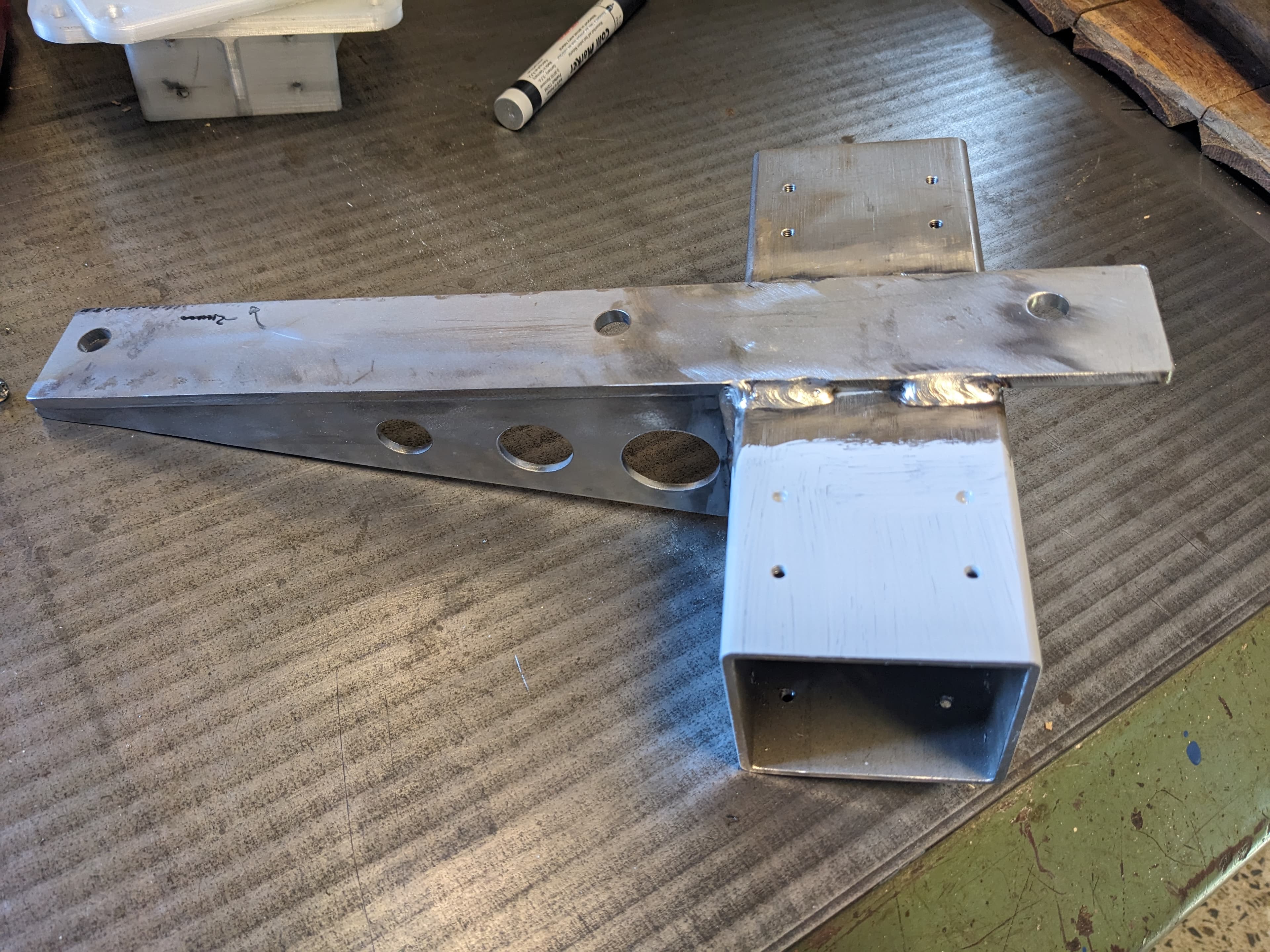
The carriage body is built around a 70x70x3 mm stainless steel tube section (190 mm long) and uses two pieces of 5mm steel welded on as support for the X-axis rail.
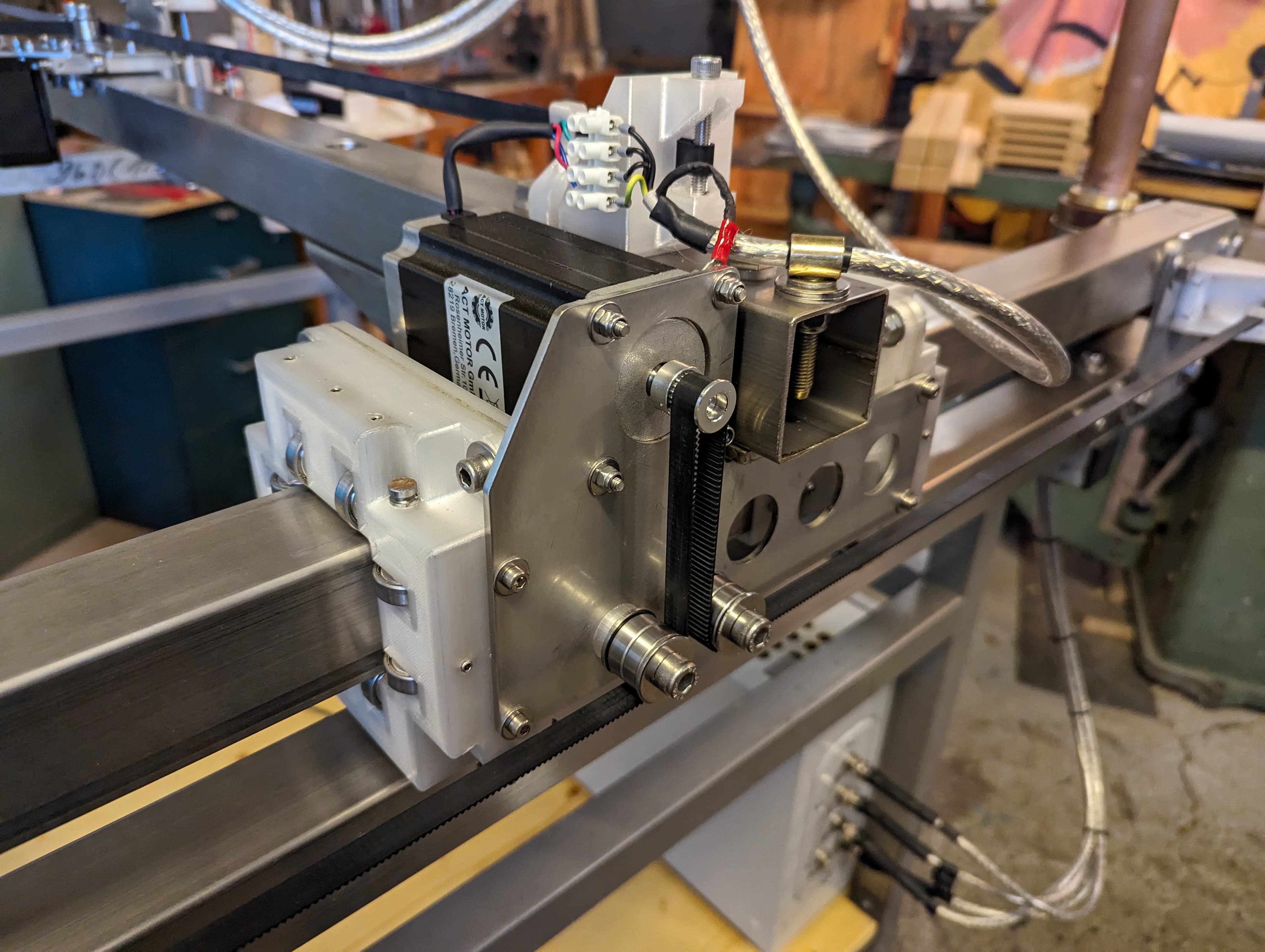
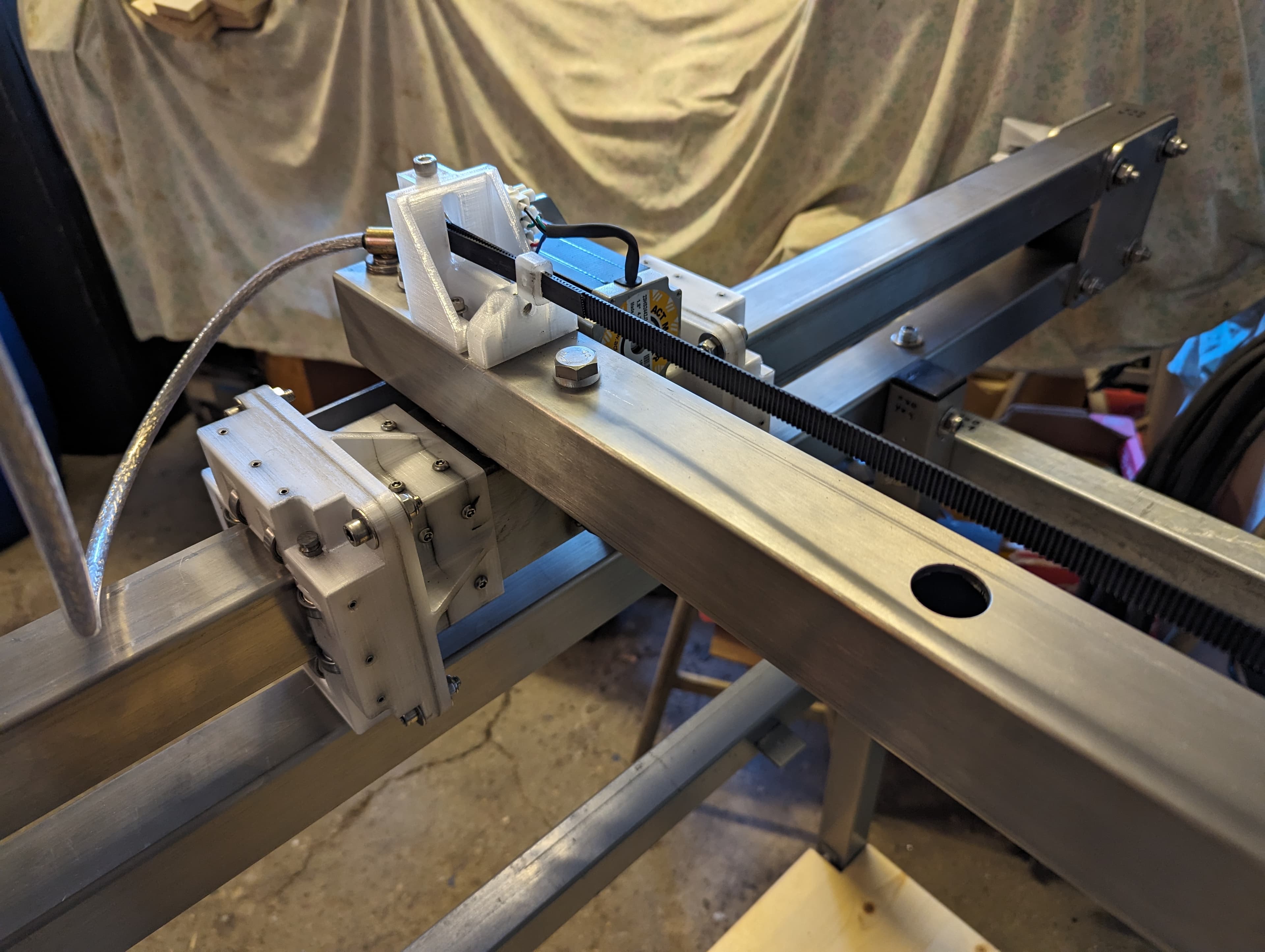
The entire Y-axis consists of two parallel 1,330 mm stainless steel tubes (upper and lower rails) joined by four laser-cut Y-plates at the ends, bolted through with M10x80 bolts. The Y-motor plate (135x228x3 mm laser-cut steel) mounts a NEMA 23 motor (3 Nm, 4.2A) with a GT2 pulley driving the timing belt.
2.5 Z-Axis
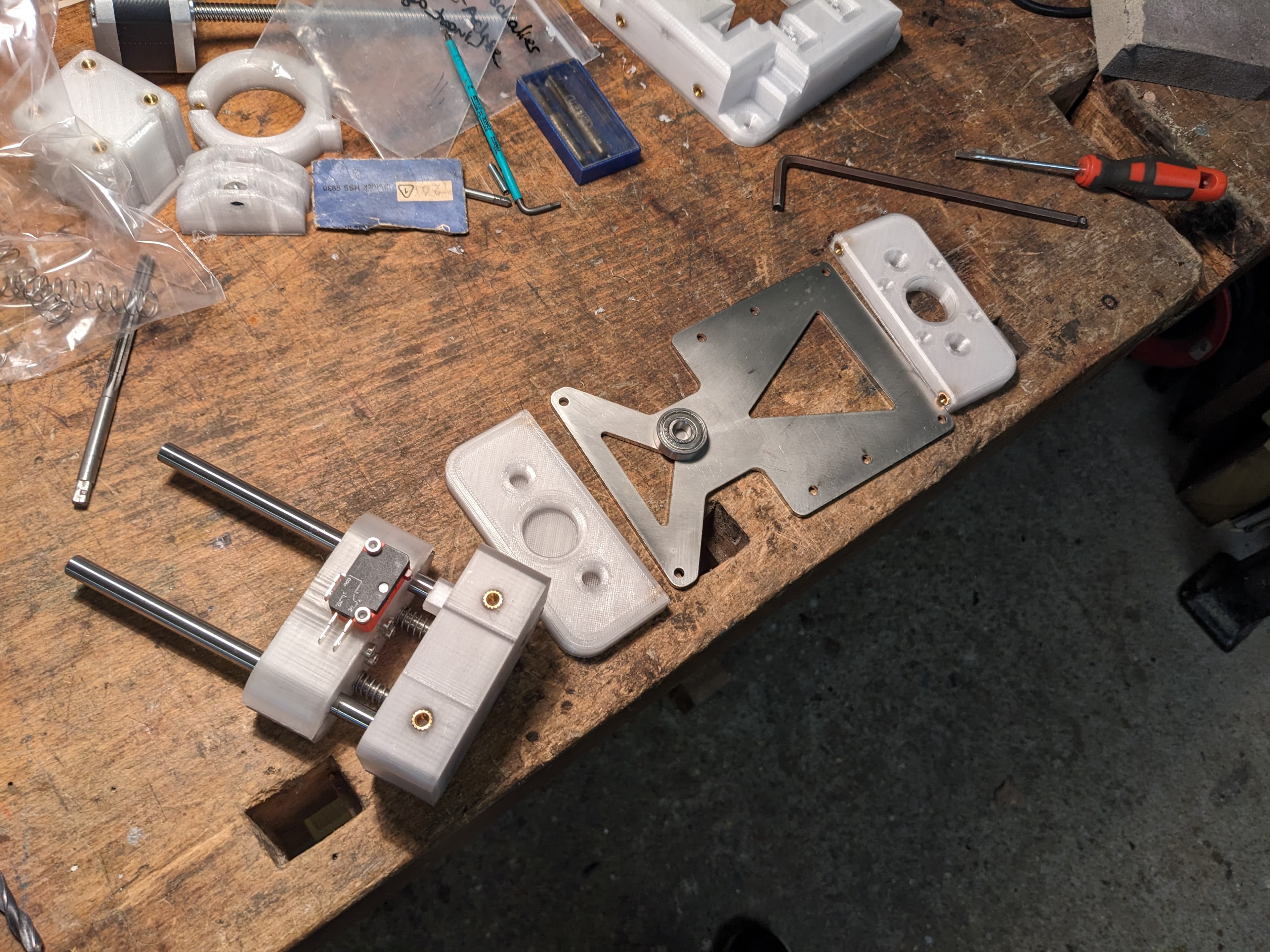
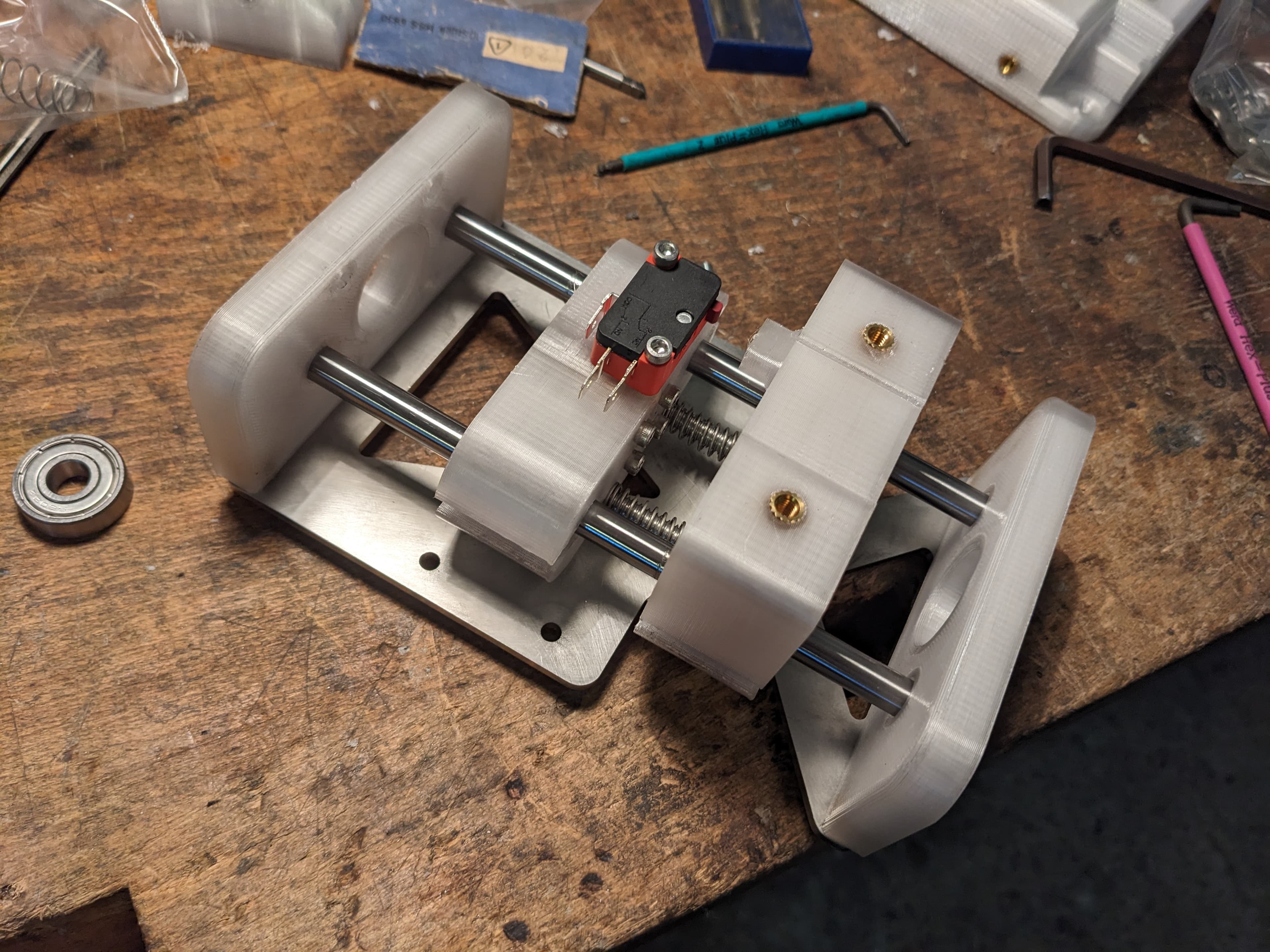
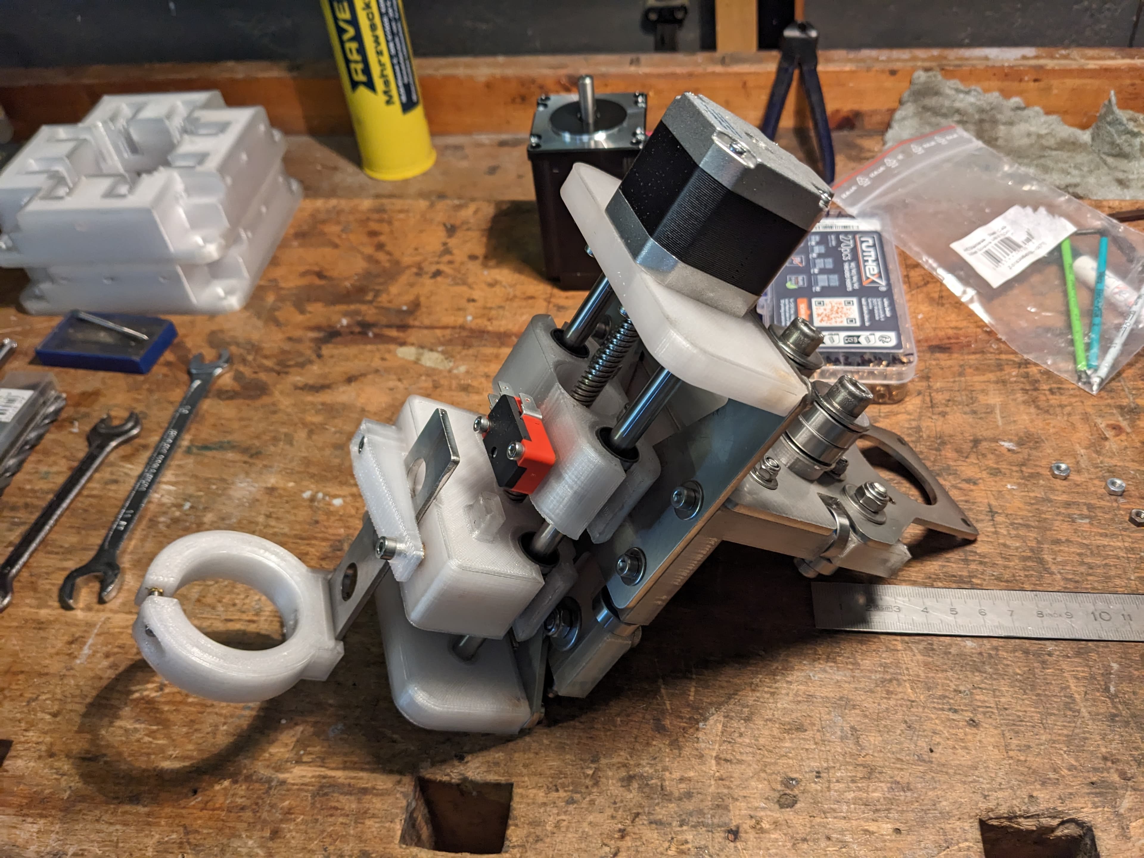
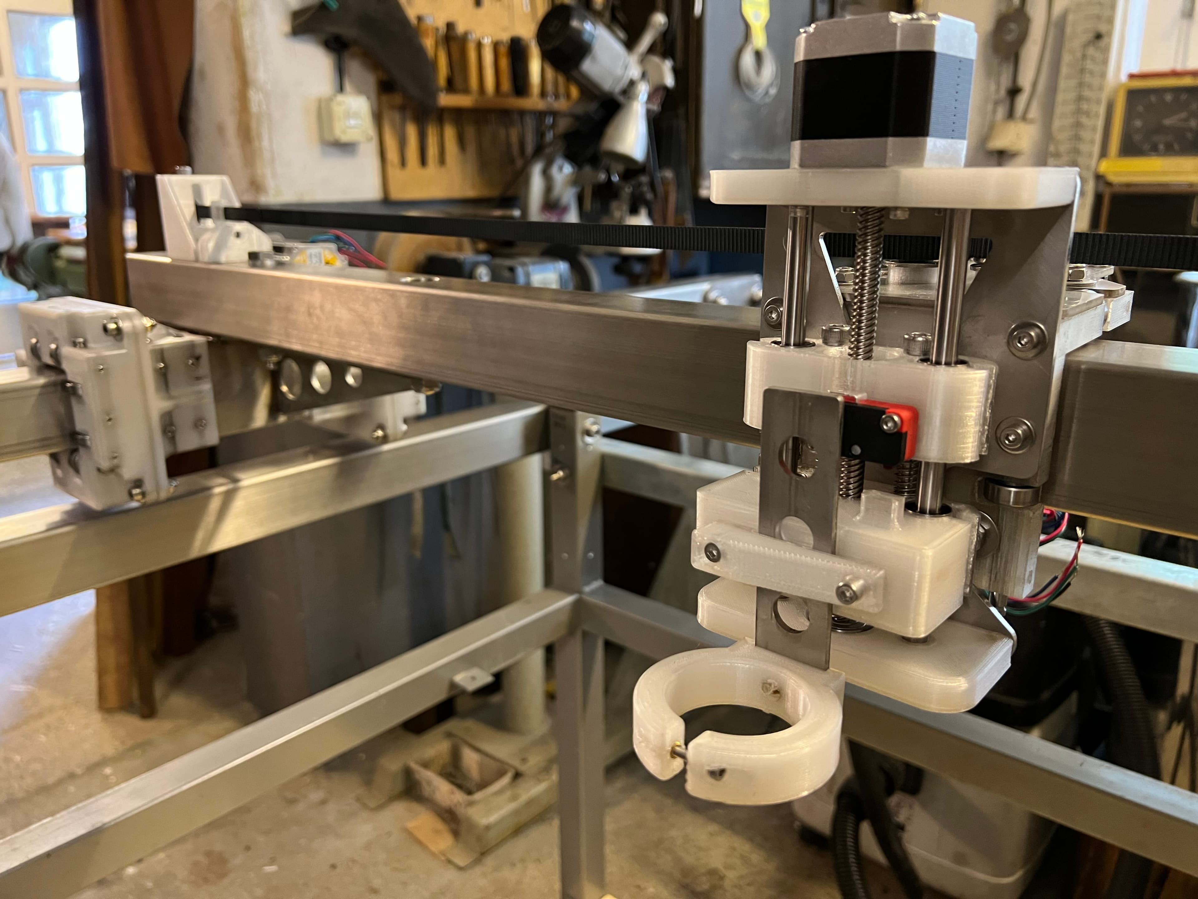
The Z-axis consists of multiple 3D-printed, laser-cut and standard parts utilising a floating head mechanism.
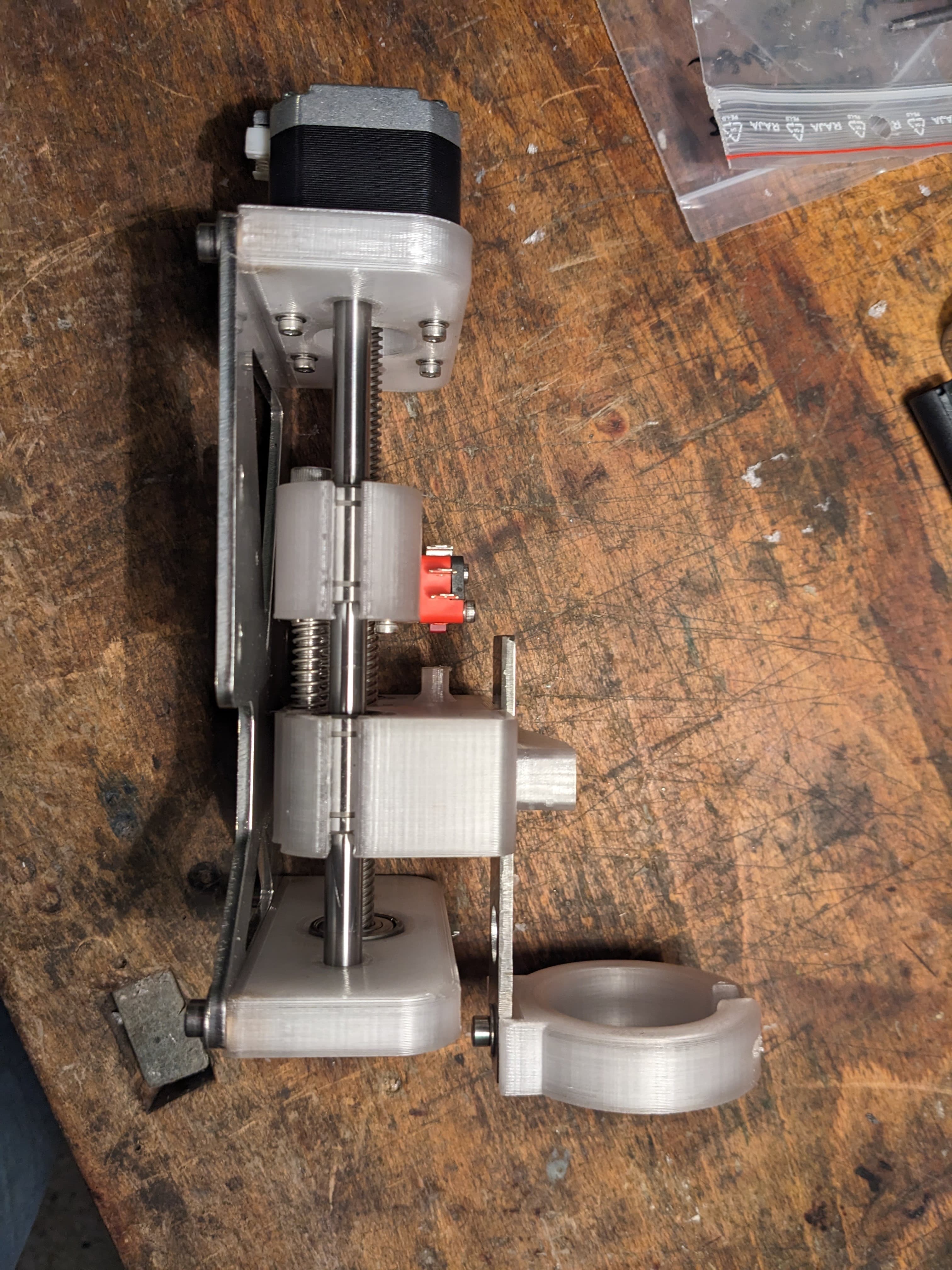
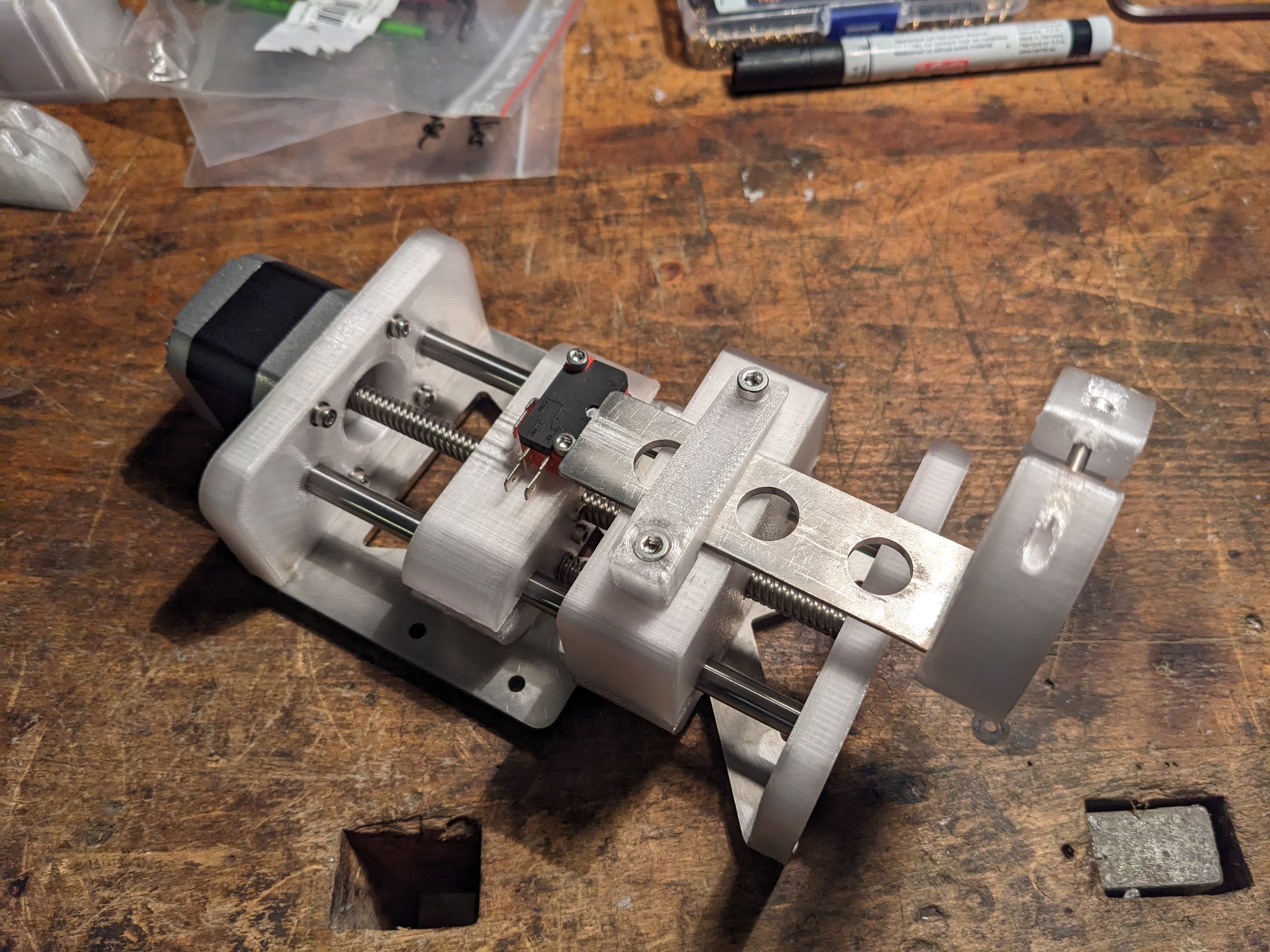
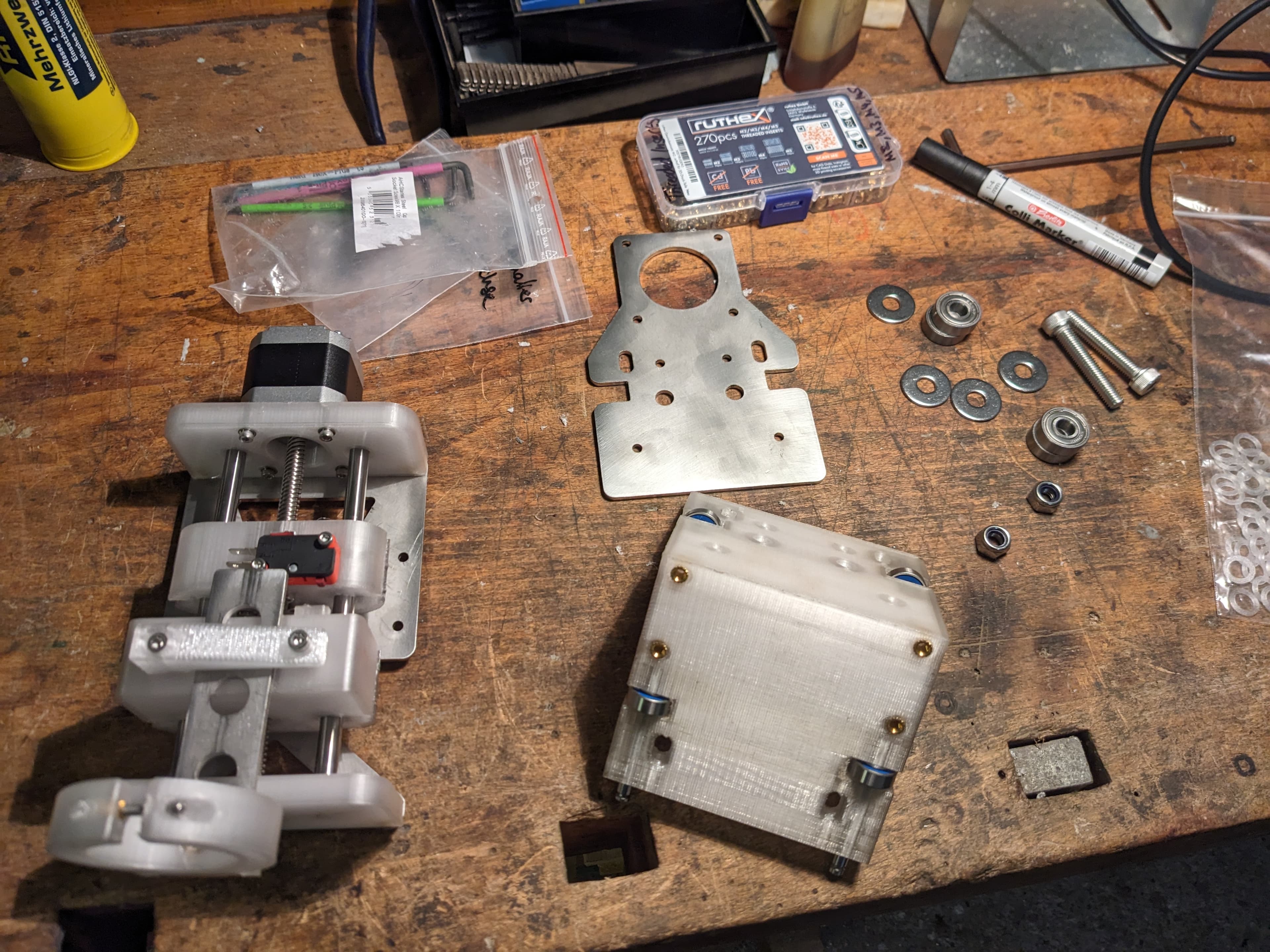
The spring-loaded float mechanism lets the torch deflect upward on contact until hitting the limit switch. This enables automatic setting of both pierce and cut height for every cut rather than adjusting manually every time.
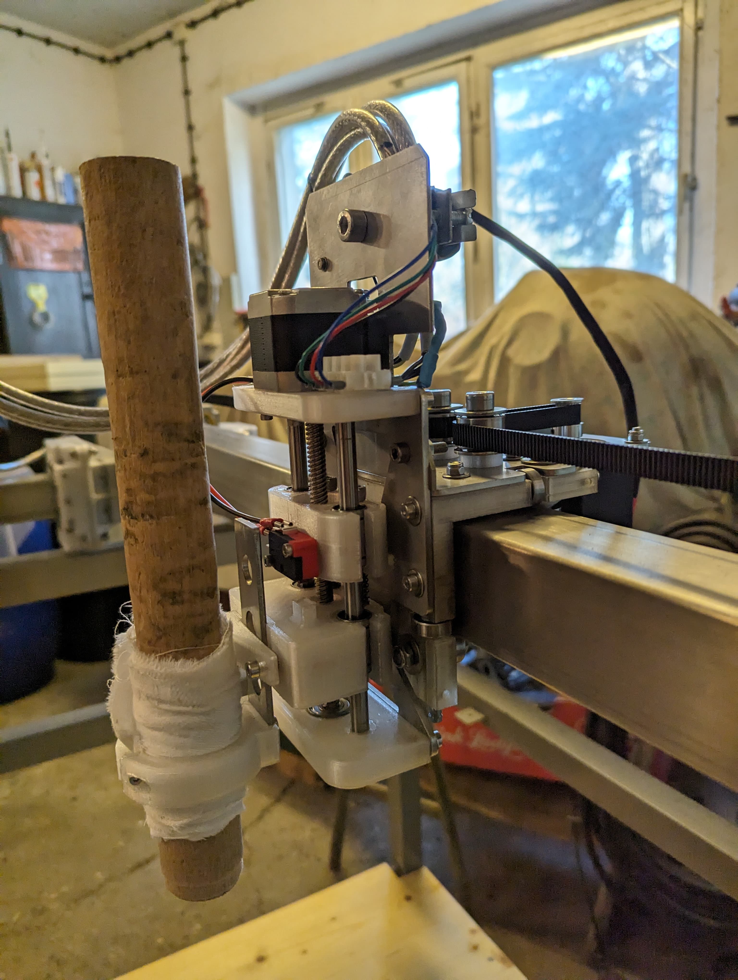
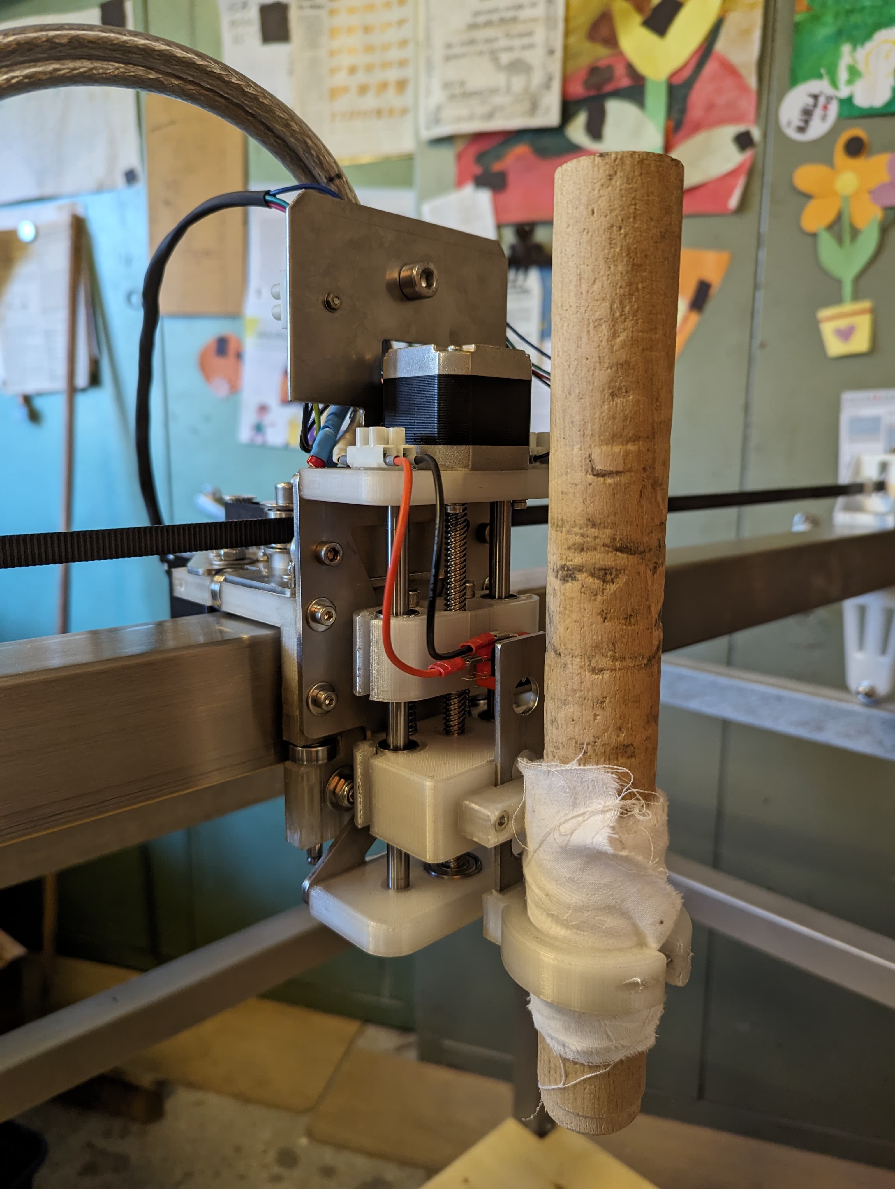
A NEMA 17 with a 150 mm integrated T8 lead screw provides vertical motion, guided by two 8 mm precision shafts with LMU8 linear bearings. The entire Z-axis is bolted to the X-carriage.
2.6 Assembly
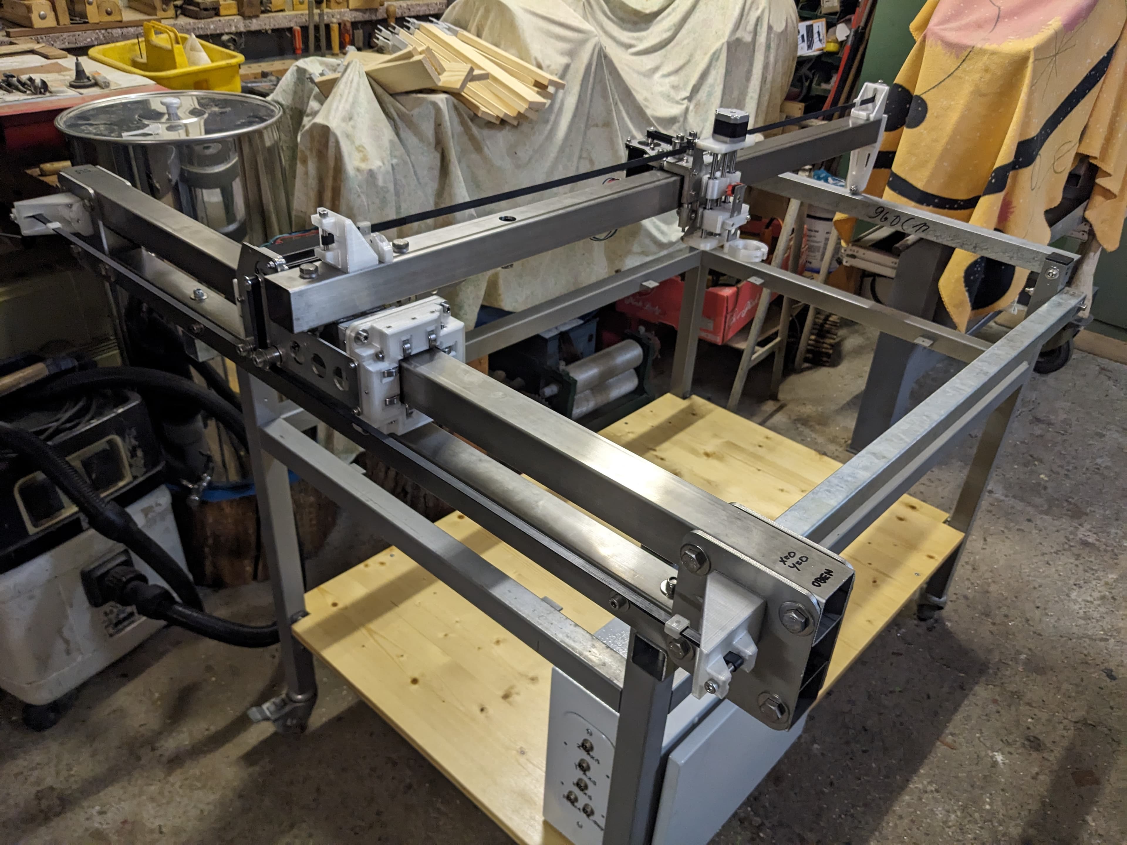
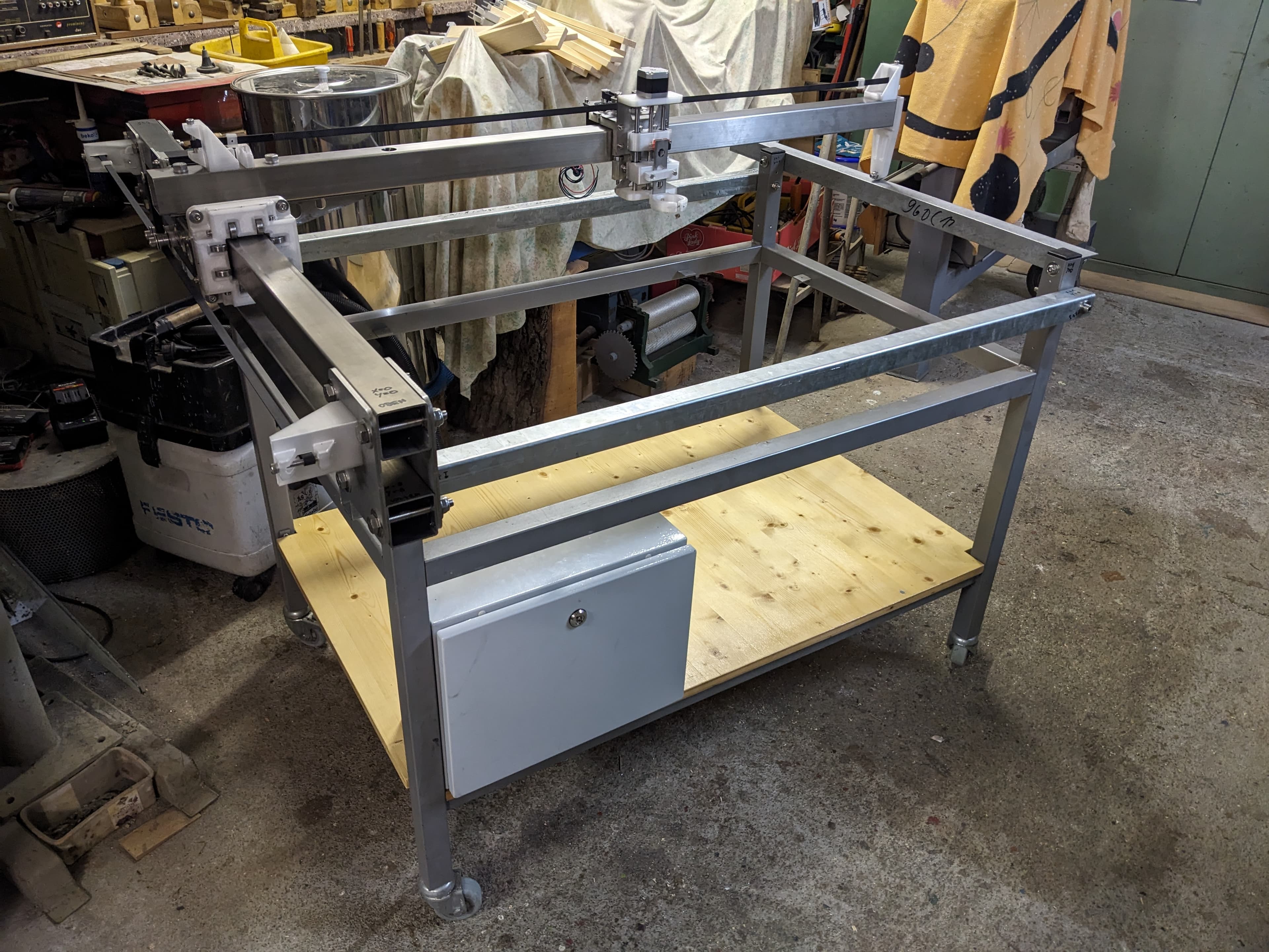
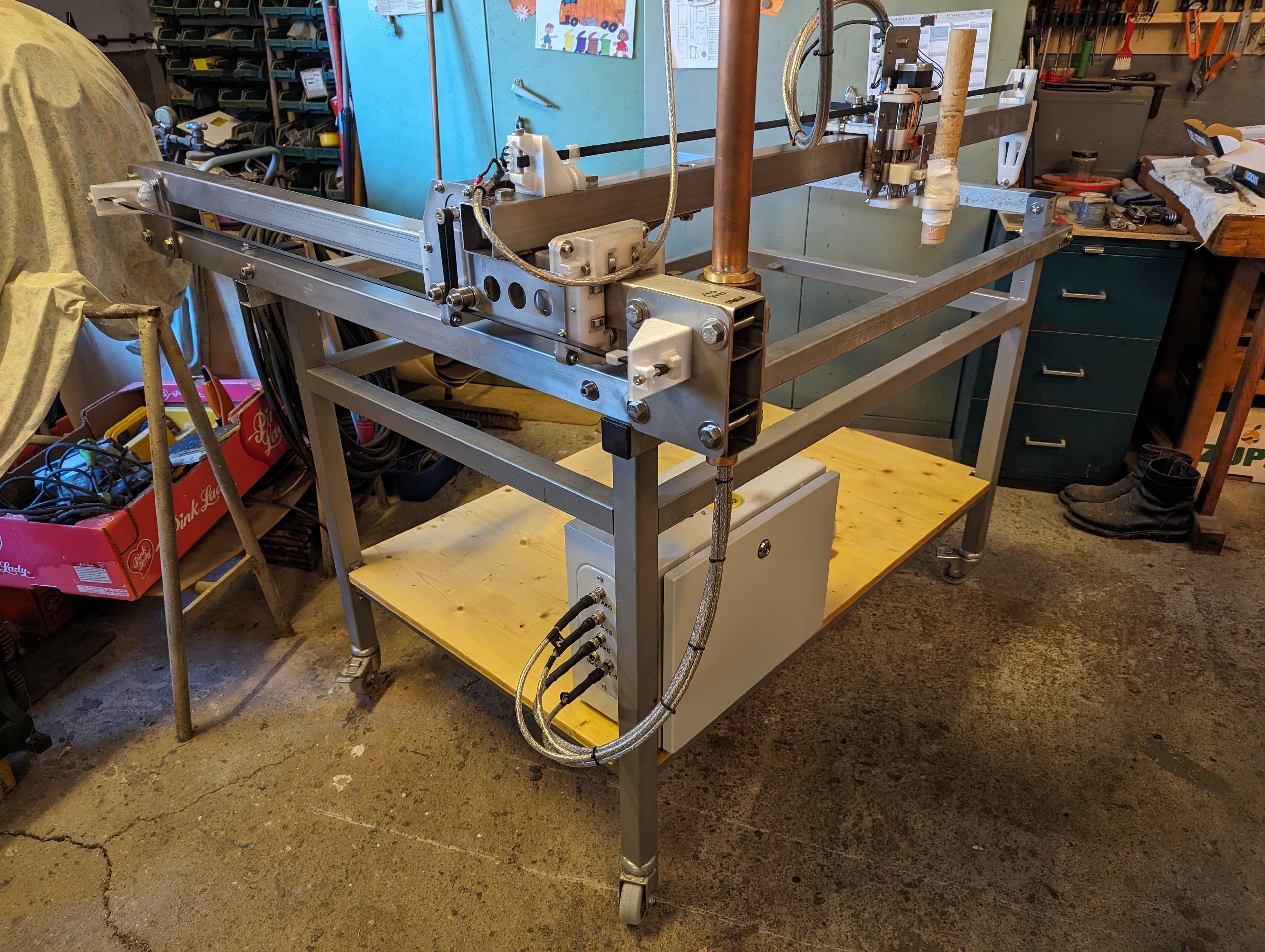
X, Y and Z axes plus the electronics housing mounted to the base frame — almost all hardware is now in place. Next step: wiring.
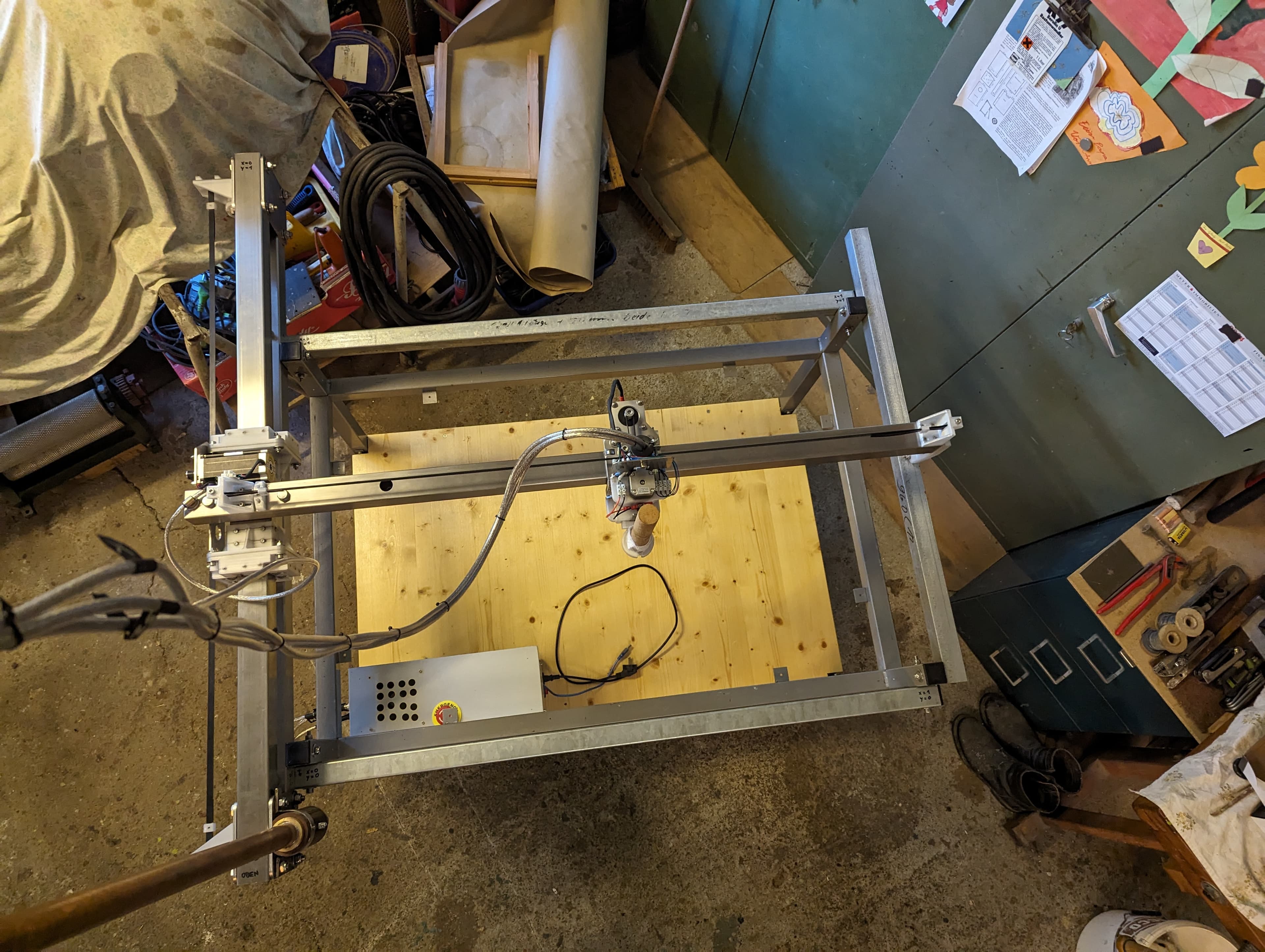
Shielded cable fitted and dry run completed. With the machine fully assembled, it was time to pack up and head to 3.
3. Disassembly and transport
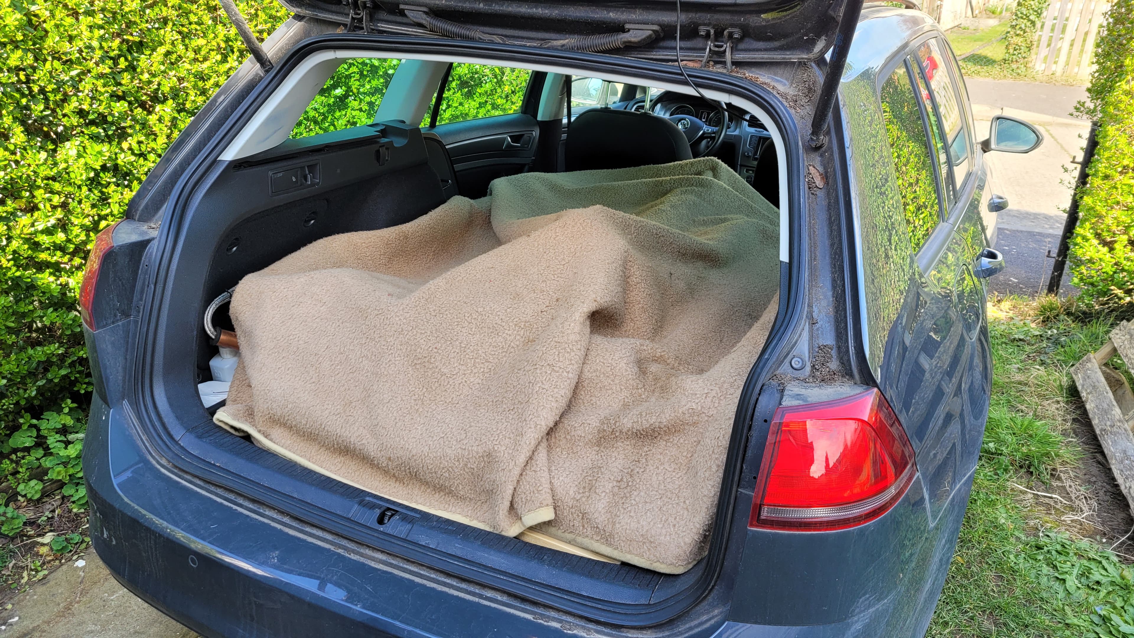
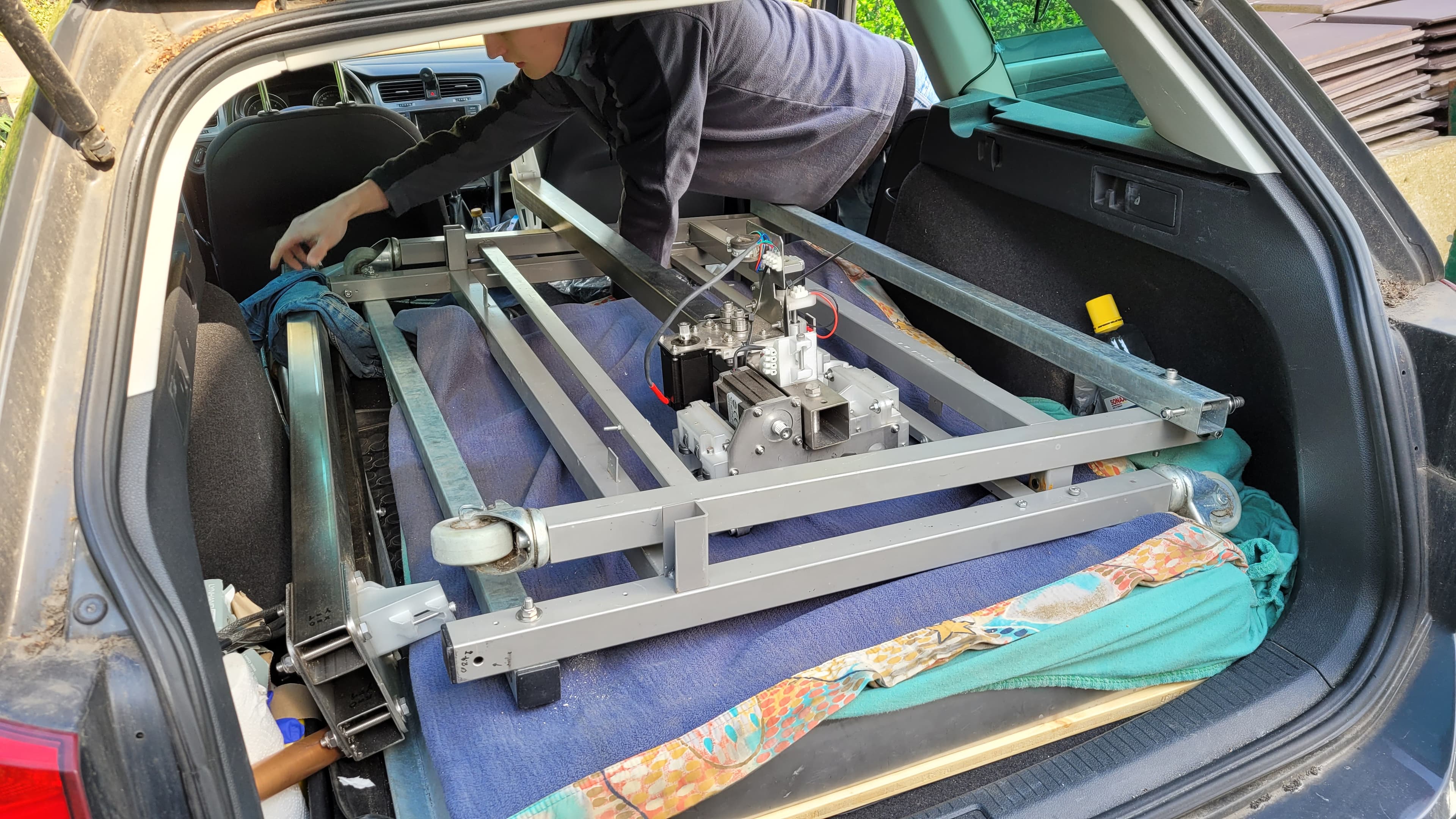
During design it was known that the whole assembly would need to make a 1,300 km trip to another country. All connectors were made as modular and disassembly-friendly as possible. The entire assembly (including water basin and supporting frame, which was additionally fabricated — no pictures) breaks down to fit in the back of a Golf estate.
4. Reassembly
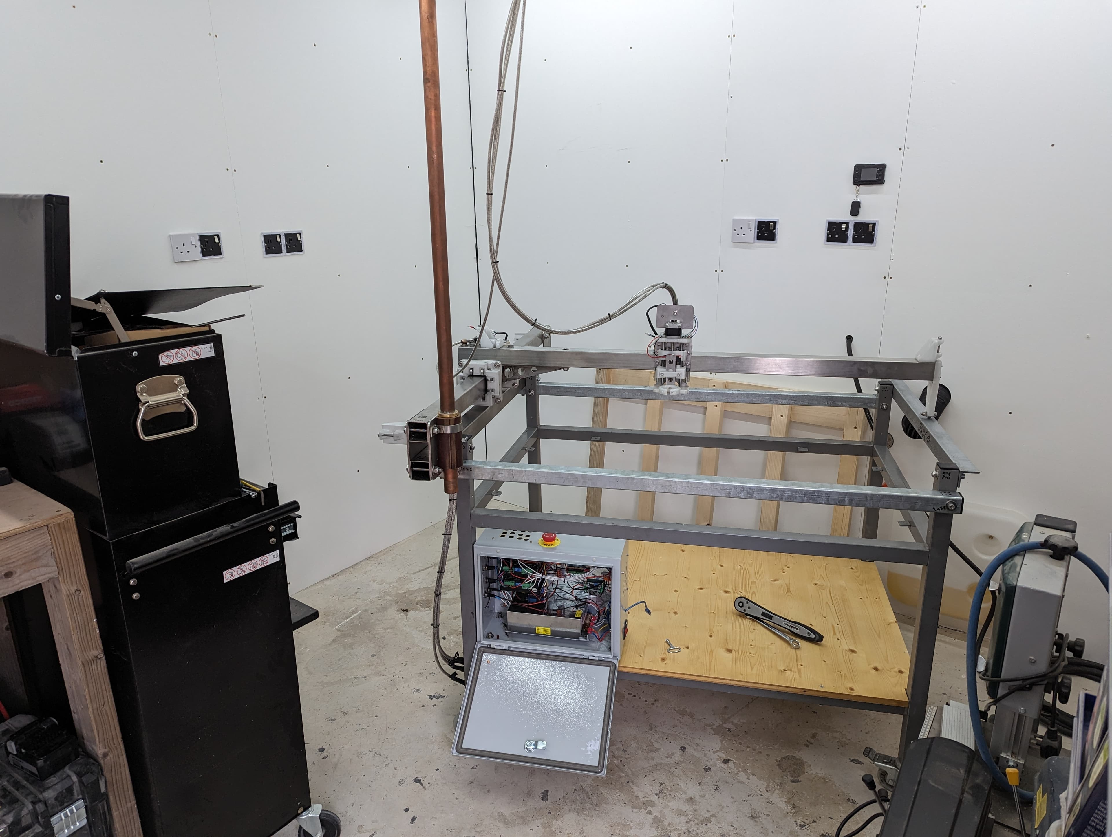
Reassembly was surprisingly quick, with final axis adjustment taking up most of the time to ensure each axis runs true.
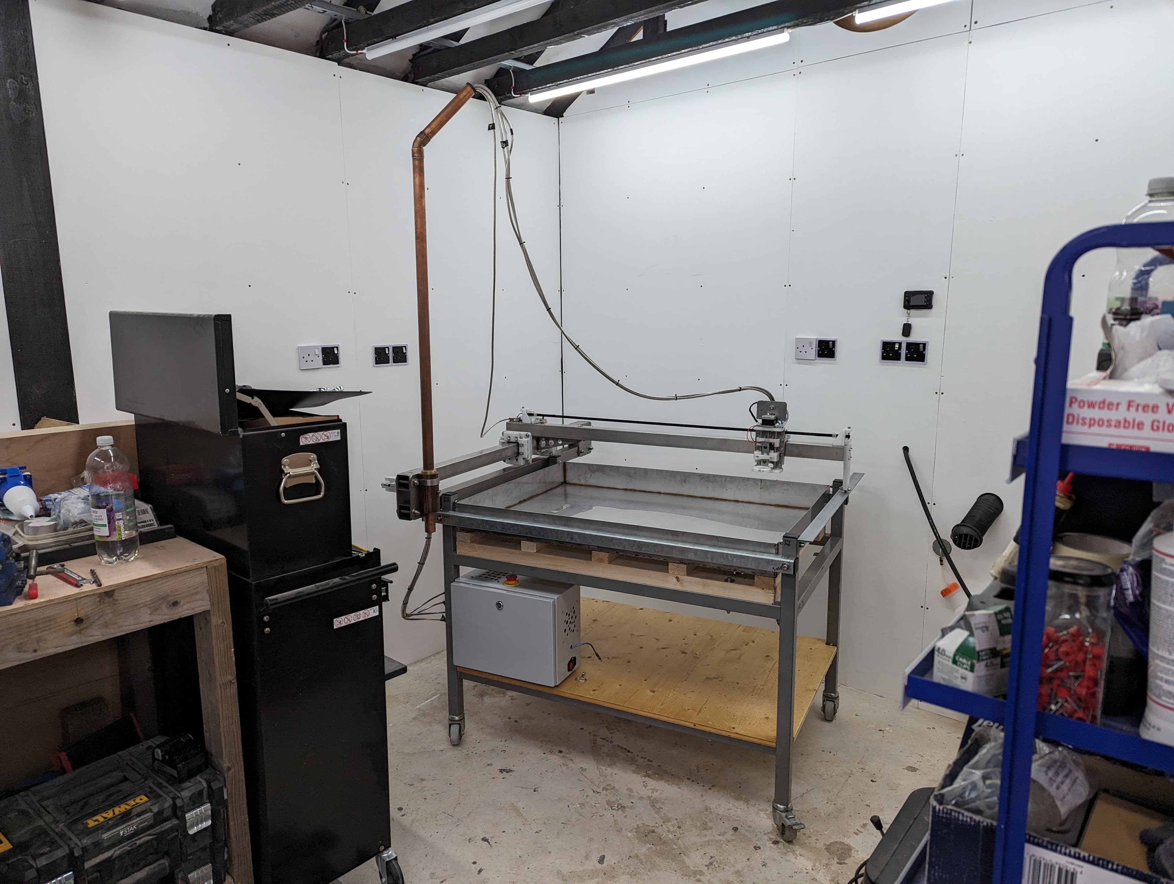
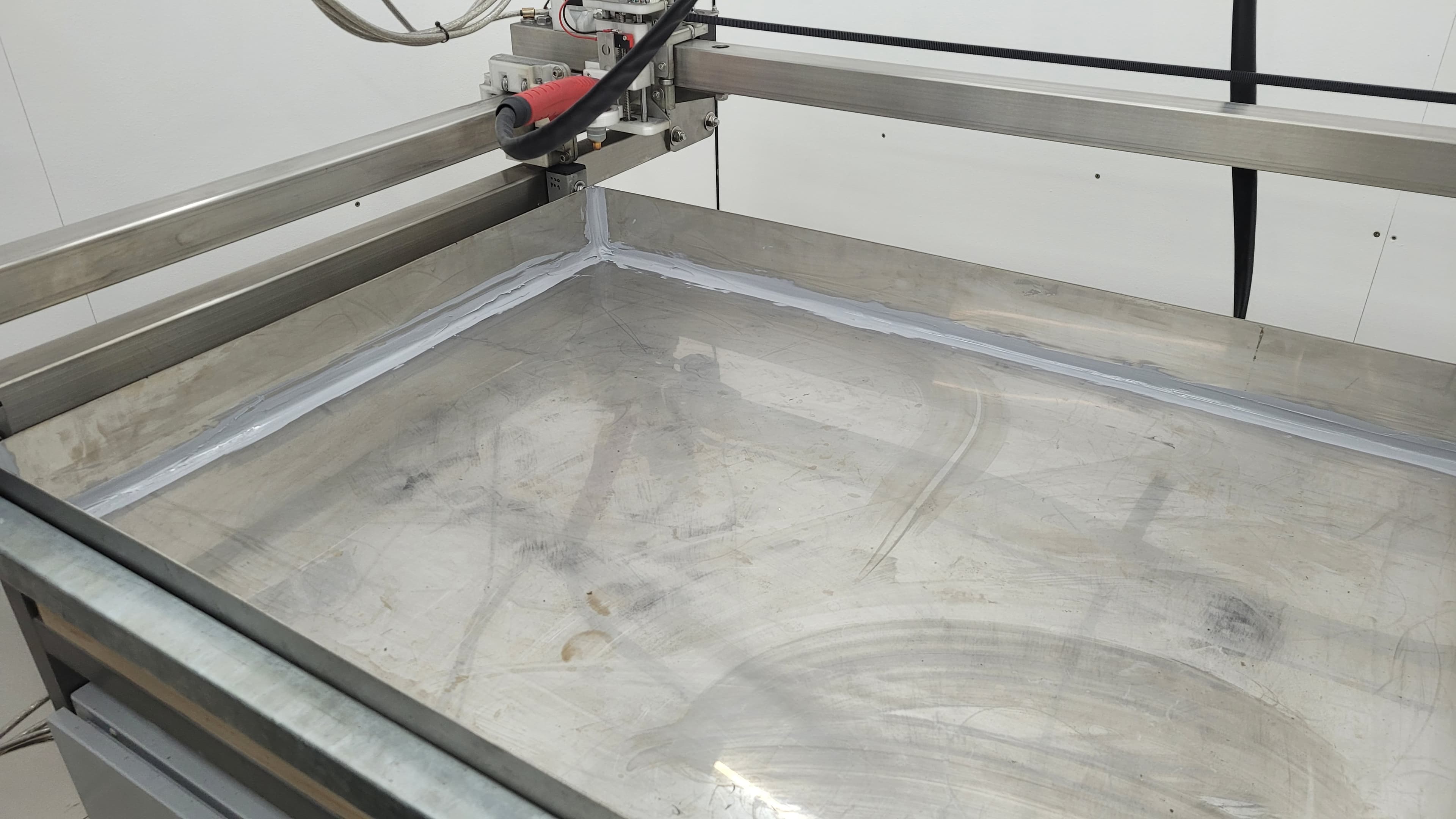
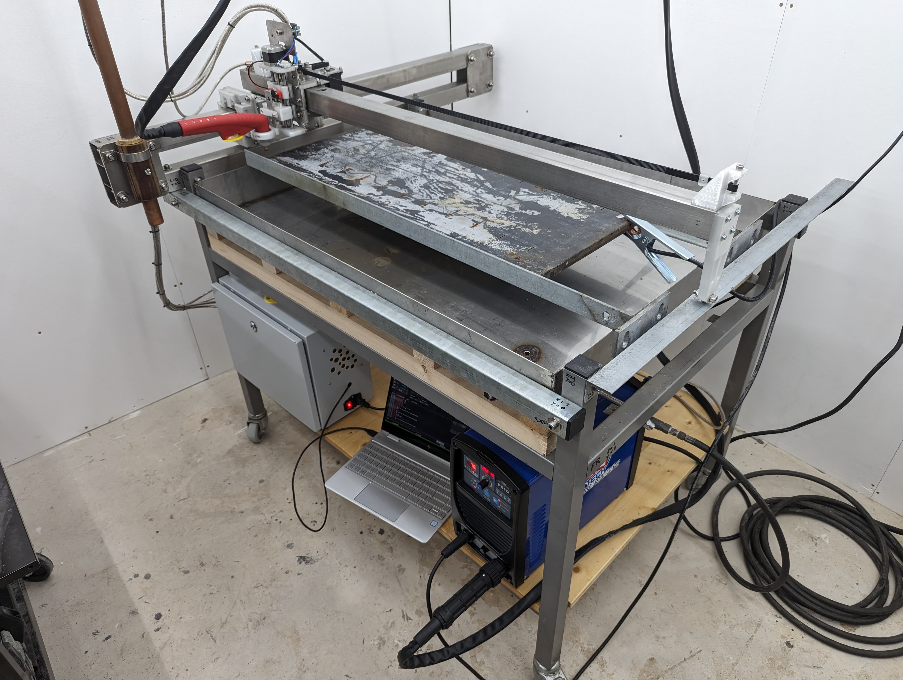
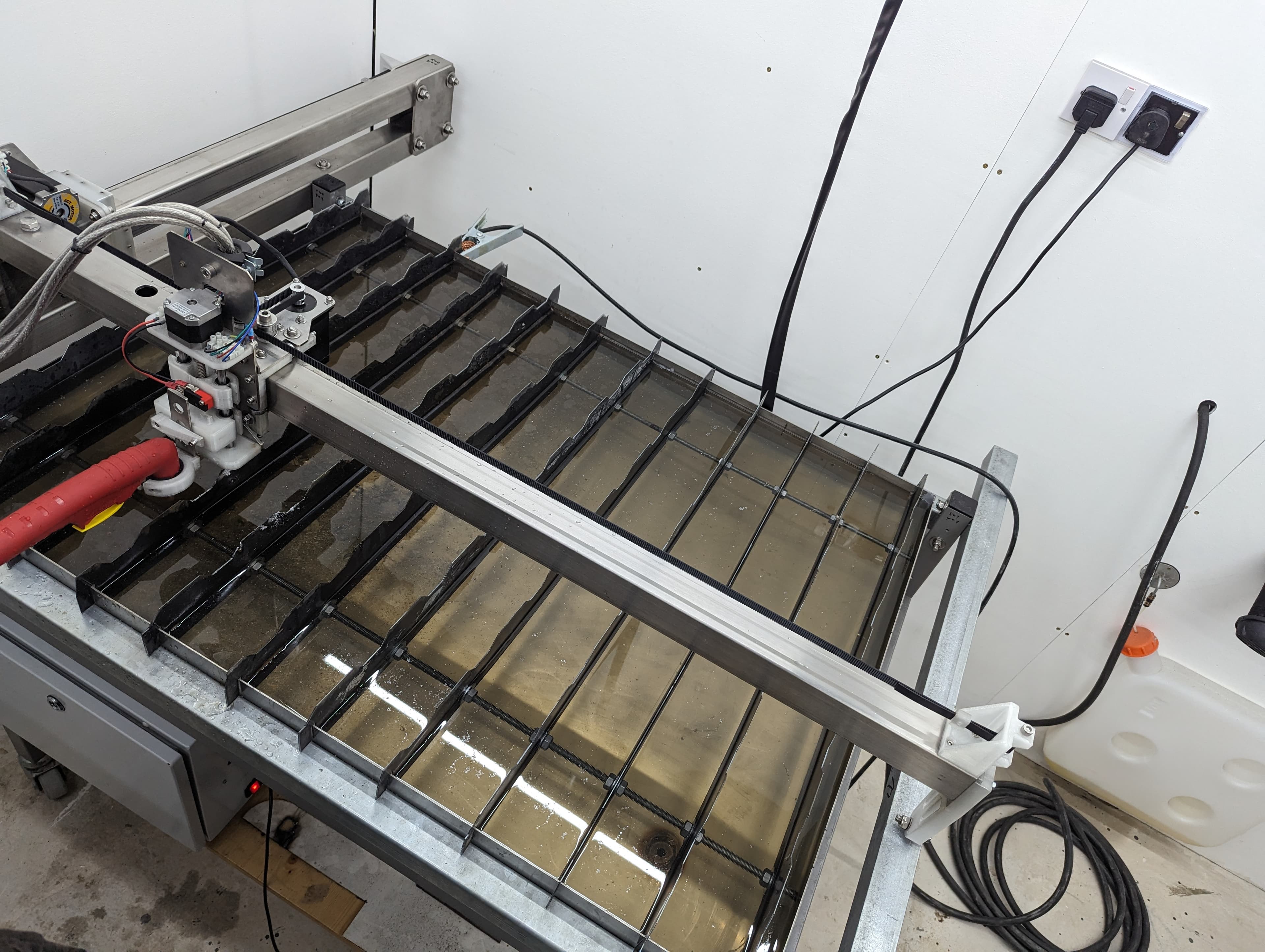
The 1mm stainless water basin was dropped in on top of the supporting frame with edges additionally sealed. A drain valve at the front right enables draining. The only thing left was to use the machine to cut the parts that would complete its own build — the cutting table slats.
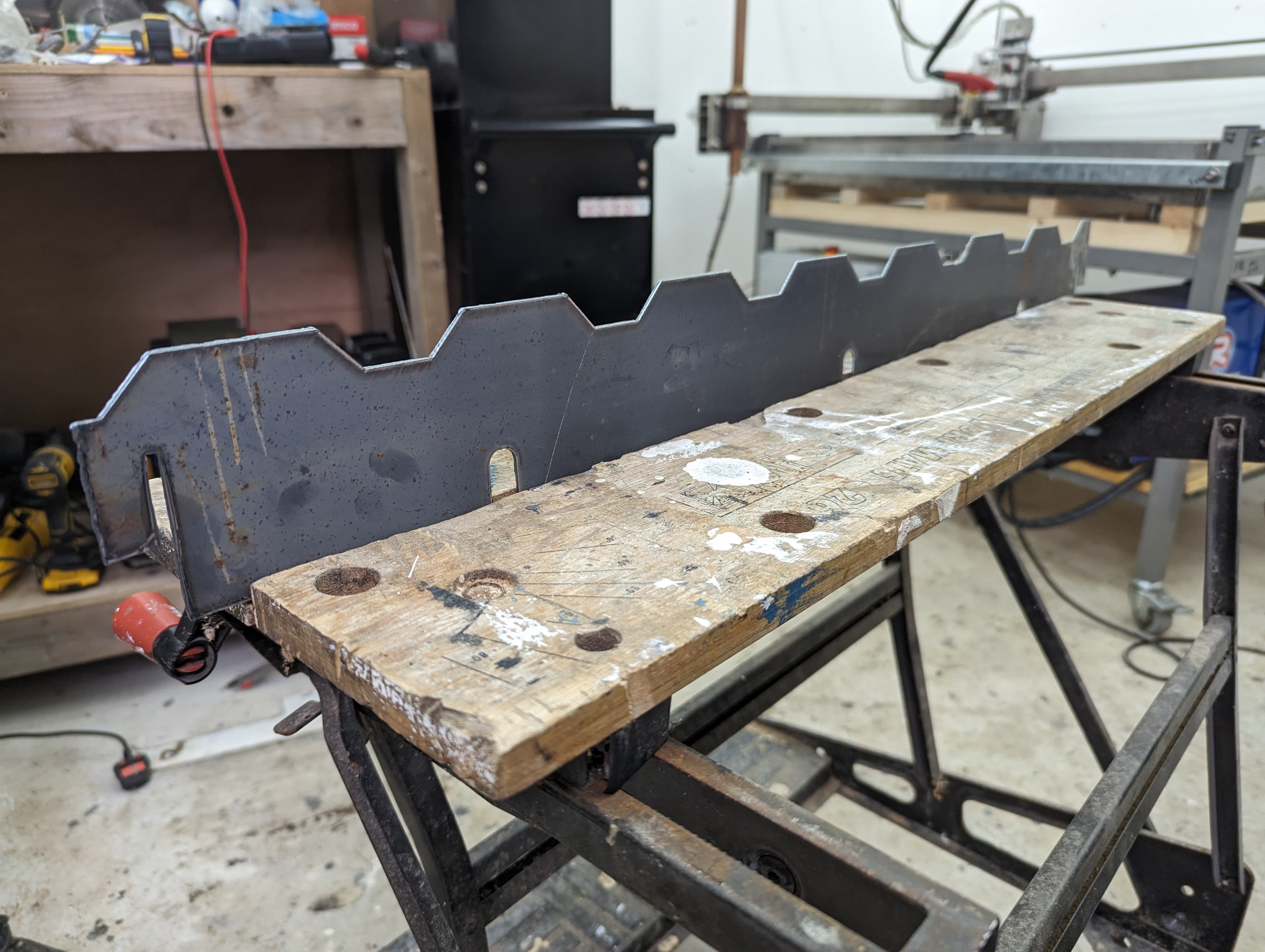
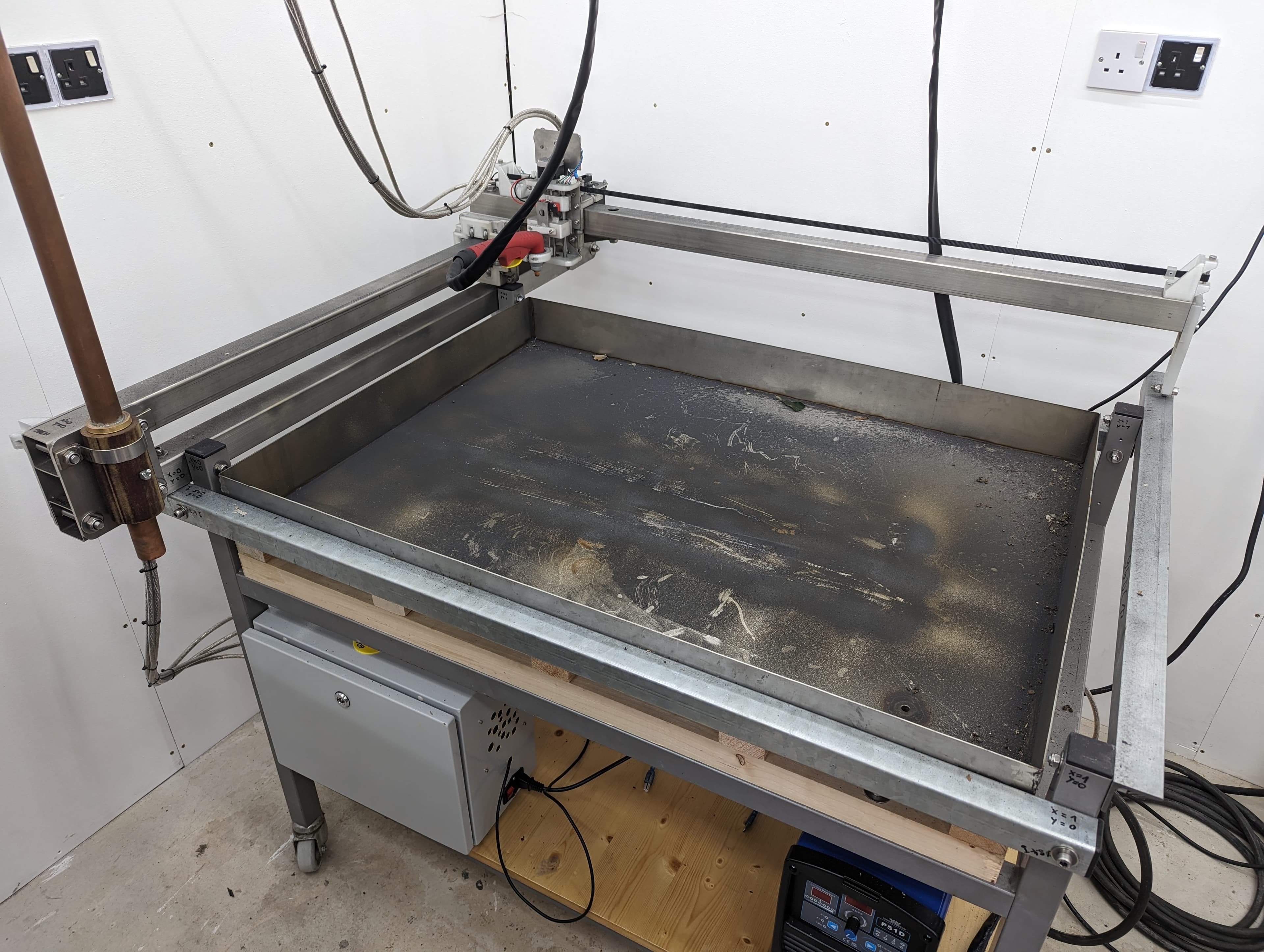
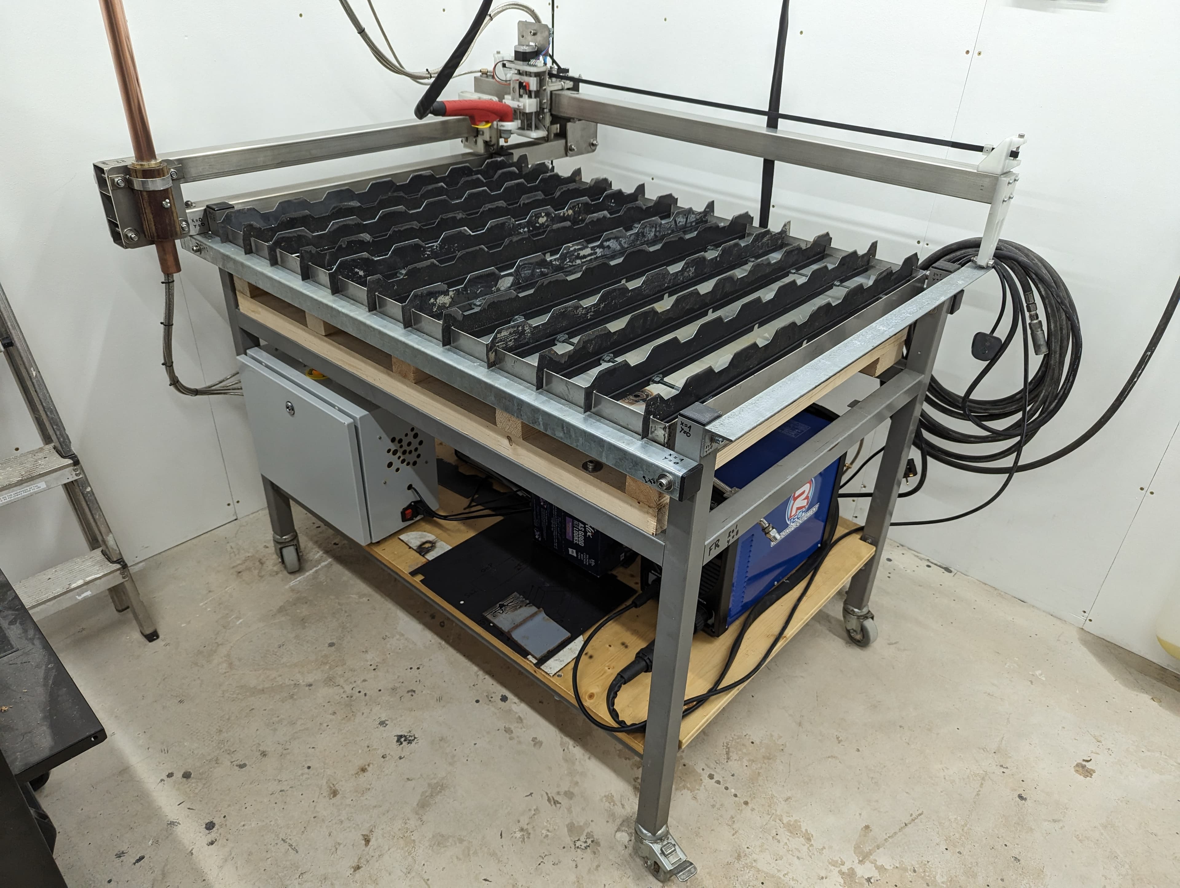
12 cutting slats were cut with a makeshift setup. The water basin covered in metal dust highlights the necessity of the water table to reduce fumes and collect dust. Machine ready for 5 - Testing.
5. Testing
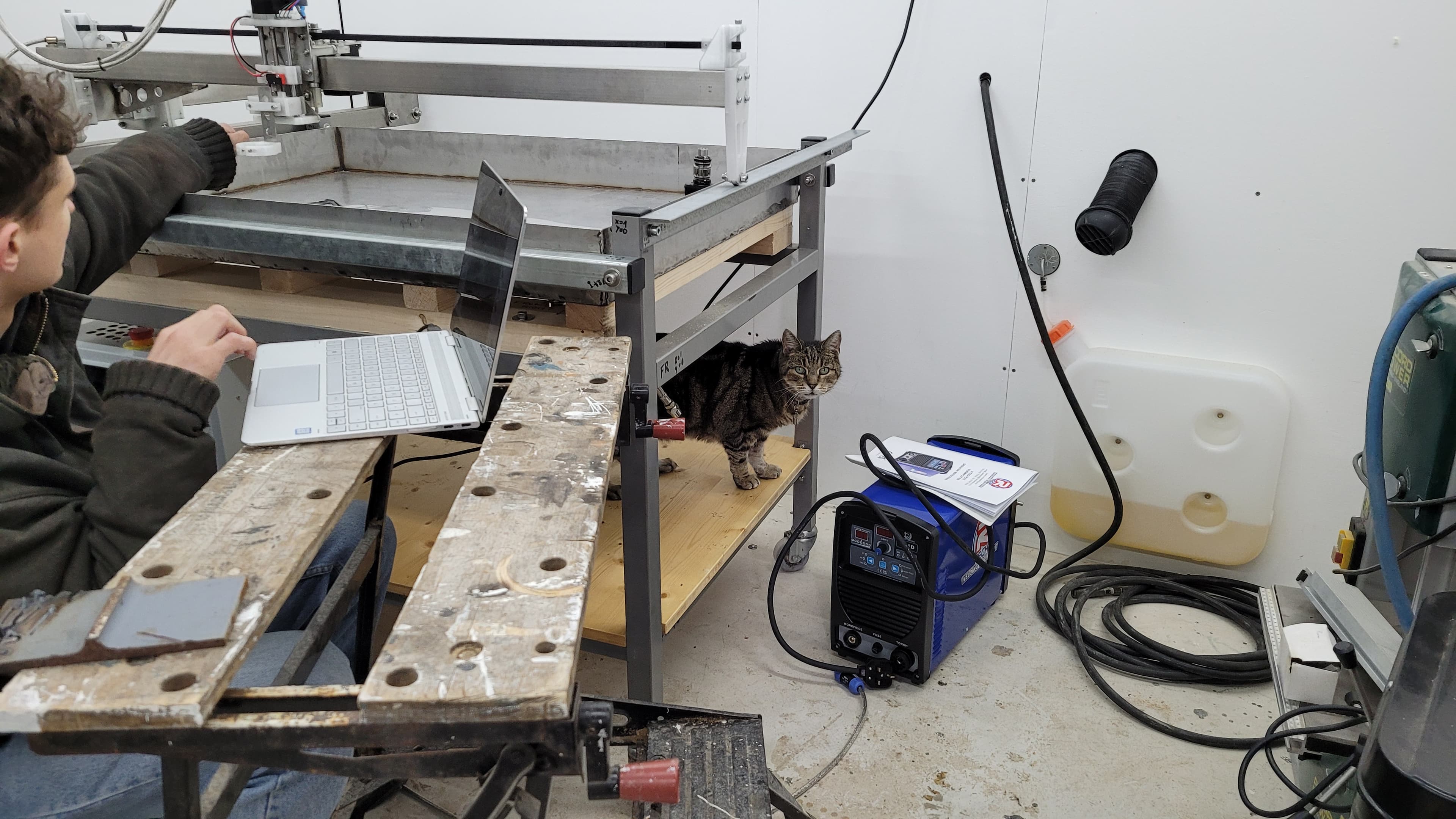
Setting up software and testing different cut parameters under the watchful eye of an inquisitive feline observer.
5.1 Example cut: 2.5mm stainless
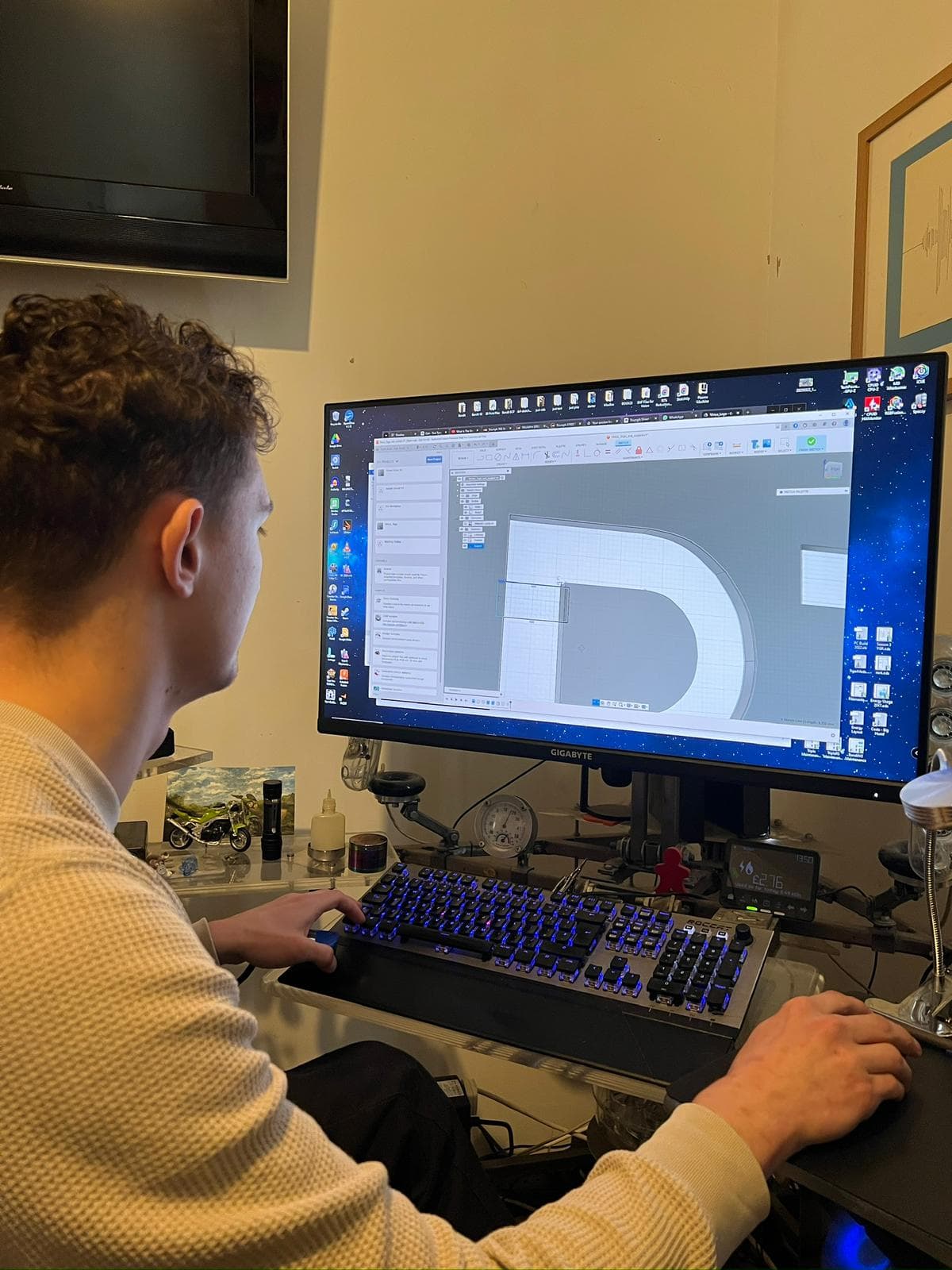
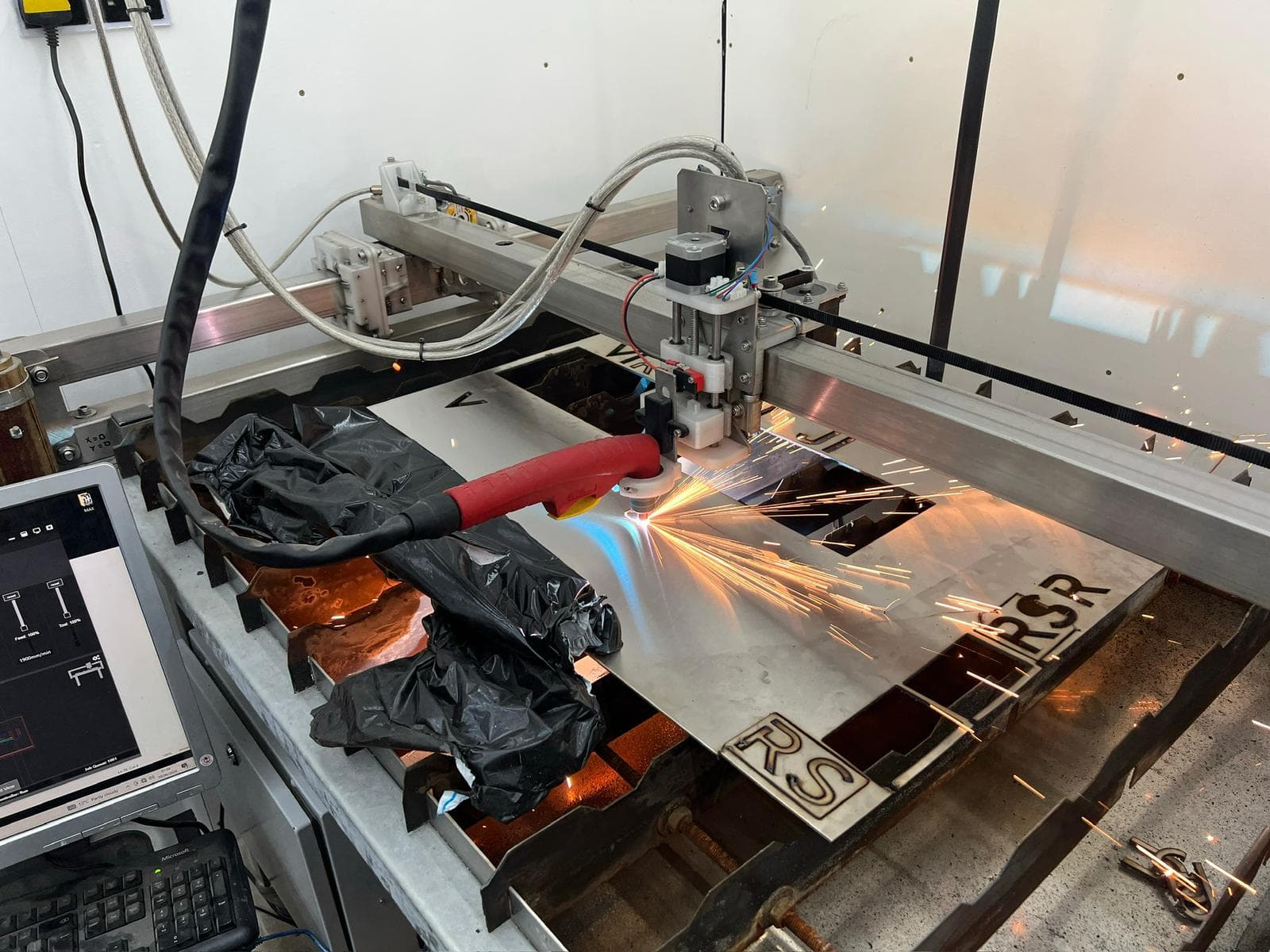
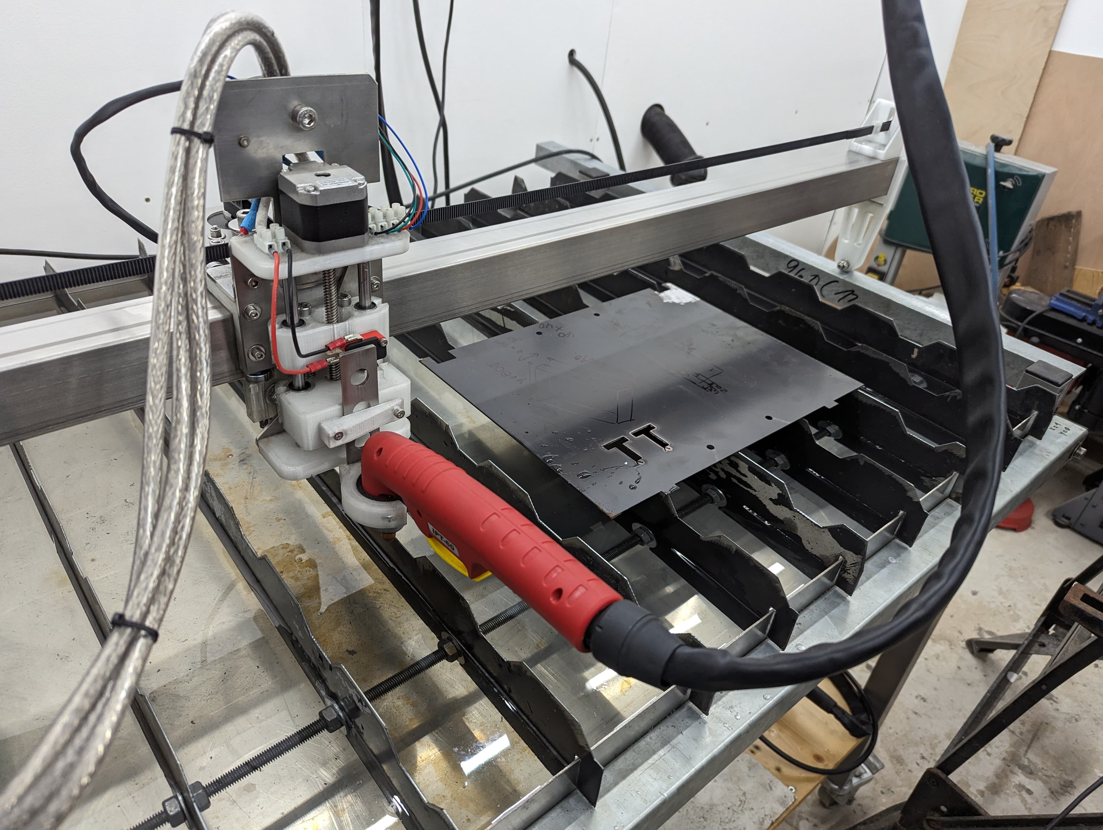
Part designed in Fusion 360, cut parameters set for 2.5mm stainless.
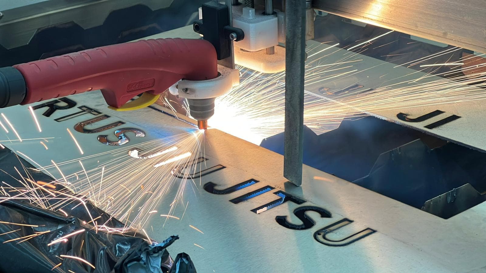
With longer cuts, warping due to thermal load requires some force to keep the sheet flat.
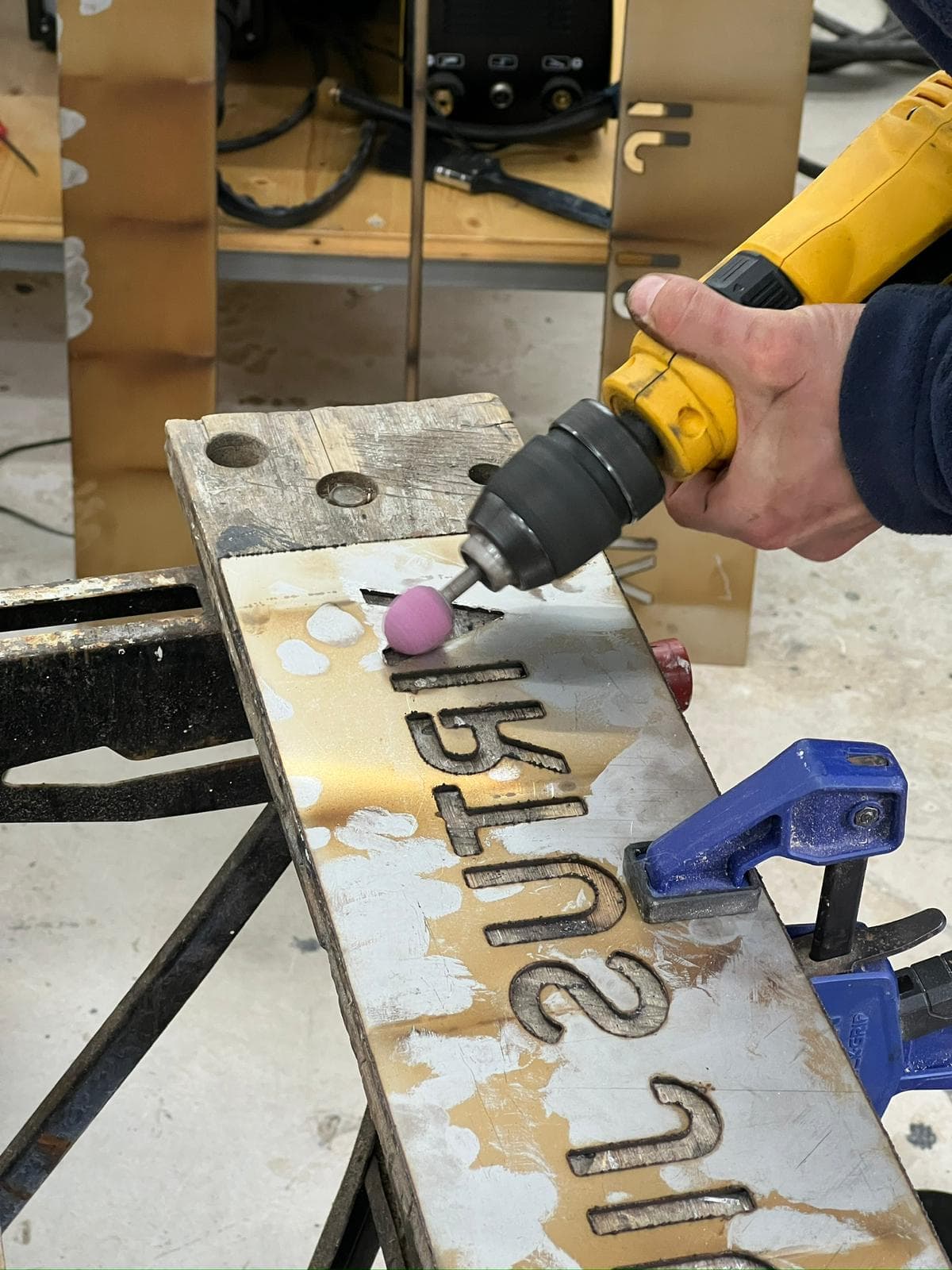
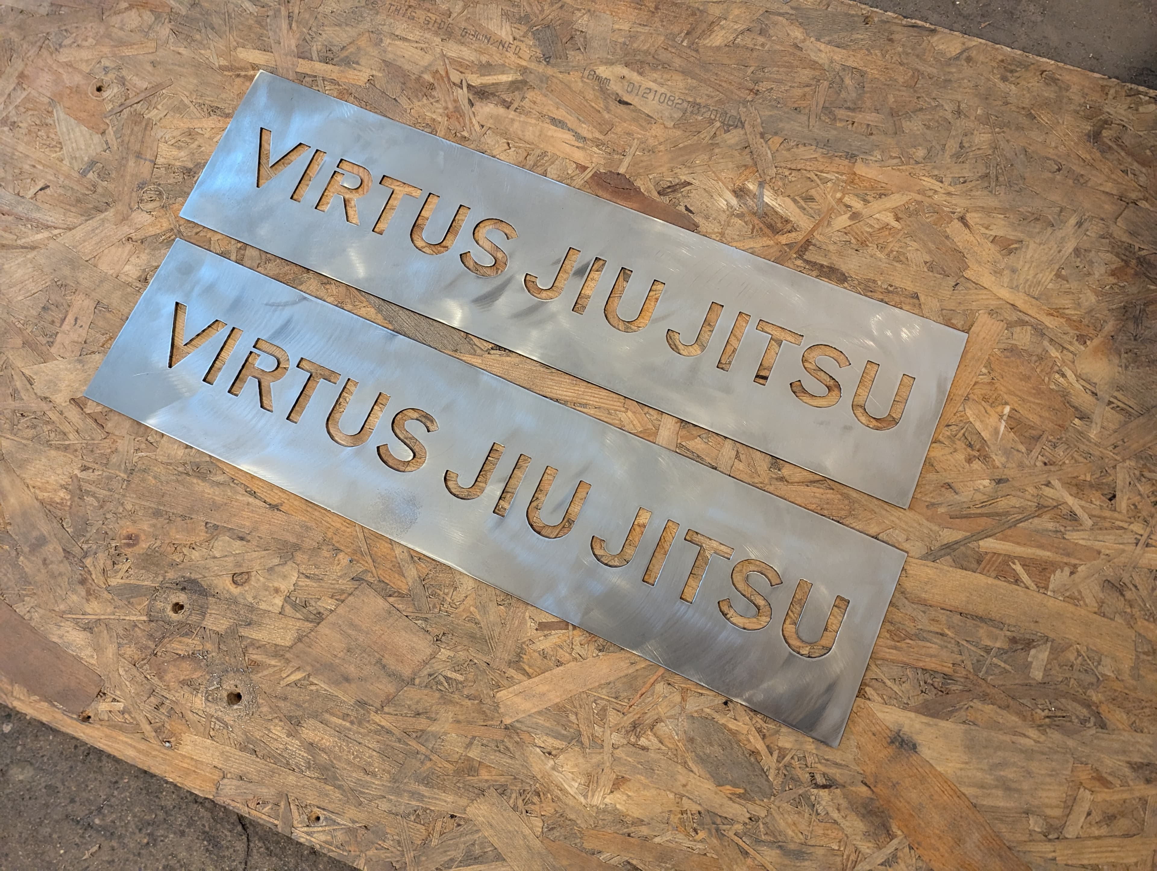

Edges need a light deburr but quality is good. Dialling in parameters correctly gives accuracy of around 0.1 mm over the full cutting length.
Software pipeline
The workflow from design to cut uses three pieces of software in sequence.
Fusion 360 CAD — Part geometry is designed or imported here, producing a .f3d file.
Fusion 360 CAM — All cut parameters are configured here: toolpaths, cut height, cut speed, pierce delay, contour ordering, and lead-in geometry. The OpenBuilds postprocessor (.cps file, loaded once) converts the CAM output into GRBL-compatible G-code.
OpenBuilds CONTROL — Connects to the Arduino over USB, sends G-code to the machine, and provides manual jogging for setup and alignment. Handles feed hold, cycle start, and homing sequences.
Choosing a plasma cutter
Not every plasma cutter is suitable for CNC use. These are the key considerations:
High vs low frequency start — High-frequency start cutters radiate significant EMI that can damage microcontrollers and electronics. Low-frequency "blowback" start cutters use air pressure to initiate the arc and are far more CNC-friendly. Technically HF machines can be made to work with extensive shielding and grounding modifications, but it's not worth the hassle.
Pilot arc — Essentially a requirement for CNC. A pilot arc establishes the cutting arc without touching the workpiece, which improves reliability (the primary arc is established consistently at every cut start), reduces consumable wear, and can cut through rust or paint.
CNC port — A built-in CNC port lets you connect directly to a relay in the control box for torch on/off signalling. Without one you'd need to splice into existing cables inside the machine.
Cutting power — As a rough guide, 20A cuts about 3.1 mm of mild steel, with an additional 3.1 mm per extra 10A. Stainless and aluminium max thickness is roughly 35-40% less. 60A is typically the upper limit for a 230V household supply; above that requires 400V.
Duty cycle — Most 230V cutters are rated below 100% duty cycle (based on a 10-minute period, so 60% means 6 minutes of cutting per 10). CNC benefits from higher duty cycles since there's no pause between cuts. Running at lower amperage improves the duty cycle — a 50A machine might be 60% at full power but 100% at 35A.
Air supply — The compressor needs to deliver sufficient sustained airflow for blowing away molten metal, cooling the torch, and focusing the arc. Check the plasma cutter's CFM requirements against your compressor's continuous output.
Downloads (Will be added soon...)
CAD Files
The full build CAD files as STEP.
cad/
├── 01_cnc_frame/         # base frame
├── 02_parts/             # all individual parts
├── 03_parts_standard/    # standard parts (bearings, motors, etc.)
├── 04_assemblies_sub/    # small assemblies (bearing blocks, etc.)
└── 05_assemblies_main/   # main assemblies as highlighted in text
3D Print Files
The full build print files as STL.
↓PRINT FILES (.STL)Laser Cut Parts Files
The full build laser cut files as DWG for 3mm and 5mm stainless components.
↓LASER FILES (.DWG)Wiring
Wiring diagrams for electronics components available as PDF.
↓WIRING DIAGRAMS (.PDF)Assembly Drawings
Assembly drawings used during assembly. Part names may differ slightly from the CAD folder due to a recent naming convention update.
↓ASSEMBLY DRAWINGS (.PDF)Bill of Materials (BOM)
Full build cost breakdown across the mechanical assemblies and electronics enclosure.
↓Full BOM spreadsheet (XLSX)